2013 SUBARU FORESTER heating
[x] Cancel search: heatingPage 5 of 436

2
Chapter 4: Climate control
This chapter informs you how to operate
the climate control.
Chapter 5: Audio
This chapter informs you how to operate
your audio system.
Chapter 6: Interior equipment
This chapter informs you how to operate
interior equipment.
Chapter 7: Starting and operating
This chapter informs you how to start and
operate your SUBARU.
Chapter 8: Driving tips
This chapter informs you how to drive your
SUBARU in various conditions and ex-
plains some safety tips on driving.
Chapter 9: In case of emergency
This chapter informs you what to do if you
have a problem while driving, such as a
flat tire or engine overheating.
Chapter 10: Appearance care
This chapter informs you how to keep your
SUBARU looking good.
Chapter 11: Maintenance and service
This chapter informs you when you need
to take your SUBARU to the dealer for
scheduled maintenance and informs you
how to keep your SUBARU running
properly.Chapter 12: Specifications
This chapter informs you about dimen-
sions and capacities of your SUBARU.
Chapter 13: Consumer information and
Reporting safety defects
This chapter informs you about Uniform
tire quality grading standards and Report-
ing safety defects.
Chapter 14: Index
This is an alphabetical listing of all that
’sin
this manual. You can use it to quickly find
something you want to read.
& Safety warnings
You will find a number of WARNINGs,
CAUTIONs and NOTEs in this manual.
These safety warnings alert you to poten-
tial hazards that could result in injury to
you or others.
Please read these safety warnings as well
as all other portions of this manual care-
fully in order to gain a better understand-
ing of how to use your SUBARU vehicle
safely.
WARNING
A WARNING indicates a situation in
which serious injury or death could
result if the warning is ignored.
CAUTION
A CAUTION indicates a situation in
which injury or damage to your
vehicle, or both, could result if the
caution is ignored.
NOTE
A NOTE gives information or sugges-
tions how to make better use of yourvehicle. & Safety symbol
You will find a circle with a slash through it
in this manual. This symbol means “Do
not ”, “Do not do this ”,or “Do not let this
happen ”, depending upon the context.
Page 32 of 436

1)HI–Rapid heating
2) LO–Normal heating
3) OFF –Off
A) Left-hand side
B) Right-hand side
The seat heater operates when the igni-
tion switch is either in the “Acc ”or “ON ” position.
To turn on the seat heater, press the
“LO ”
or “HI ”position on the switch, as desired,
depending on the temperature.
Selecting the “HI ”position will cause the
seat to heat up quicker.
To turn off the seat heater, lightly press the
opposite side of the current position.
The indicator next to the switch illuminates
when the seat heater is in operation.
When the vehicle ’s interior is warmed
enough or before you leave the vehicle,
be sure to turn the switch off. Rear seats
WARNING
Seatbelts provide maximum re-
straint when the occupant sits well
back and upright in the seat. Do not
put cushions or any other materials
between occupants and seatbacks
or seat cushions. If you do so, the
risk of sliding under the lap belt and
of the lap belt sliding up over the
abdomen will increase, and both can
result in serious internal injury ordeath. Seat, seatbelt and SRS airbags
1-7
– CONTINUED –
Page 122 of 436

(a) do not press the trip knob for 10
seconds or (b) open and close the driver’s
door, the fuel gauge indication will turn off.
NOTE
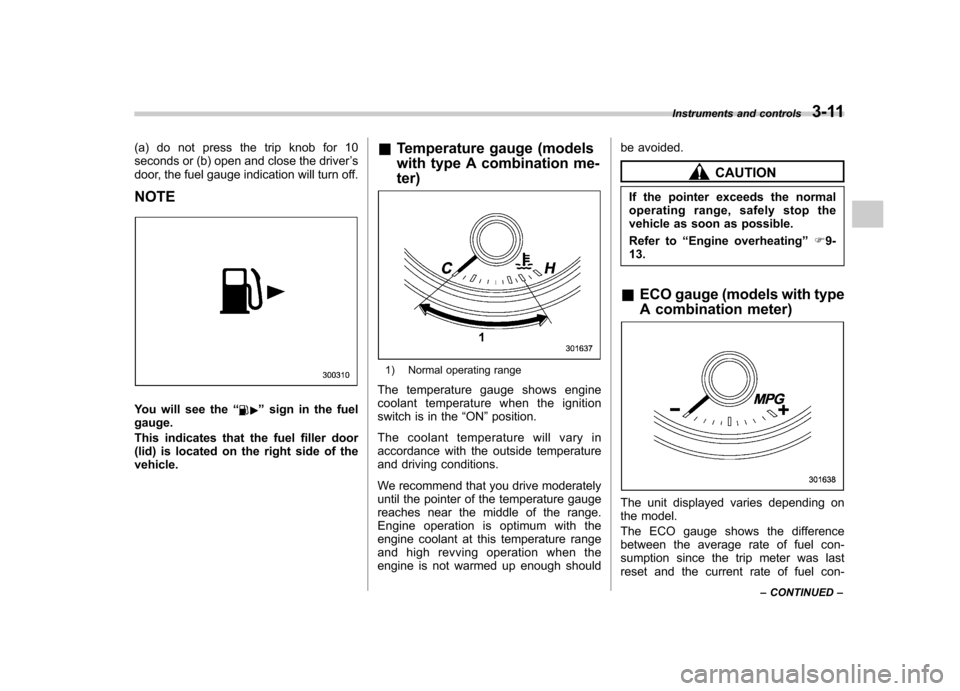
You will see the “”sign in the fuel
gauge.
This indicates that the fuel filler door
(lid) is located on the right side of thevehicle. &
Temperature gauge (models
with type A combination me- ter)
1) Normal operating range
The temperature gauge shows engine
coolant temperature when the ignition
switch is in the “ON ”position.
The coolant temperature will vary in
accordance with the outside temperature
and driving conditions.
We recommend that you drive moderately
until the pointer of the temperature gauge
reaches near the middle of the range.
Engine operation is optimum with the
engine coolant at this temperature range
and high revving operation when the
engine is not warmed up enough should be avoided.
CAUTION
If the pointer exceeds the normal
operating range, safely stop the
vehicle as soon as possible.
Refer to “Engine overheating ”F9-
13.
& ECO gauge (models with type
A combination meter)
The unit displayed varies depending on
the model.
The ECO gauge shows the difference
between the average rate of fuel con-
sumption since the trip meter was last
reset and the current rate of fuel con- Instruments and controls
3-11
– CONTINUED –
Page 127 of 436

3-16Instruments and controls
NOTE
This light also illuminates when the fuel
filler cap is not tightened until it clicks.
If you have recently refueled your vehicle,
the cause of the CHECK ENGINE warning
light/malfunction indicator light coming on
could be a loose or missing fuel filler cap.
Remove the cap and make sure nothing is
interfering with the sealing of the cap, then
retighten the cap until it clicks. Tightening
the cap will not make the CHECK EN-
GINE warning light turn off immediately. It
may take several driving trips. If the light
does not turn off, take your vehicle to your
SUBARU dealer immediately. !If the light is blinking
If the light is blinking while driving, an
engine misfire condition has been de-
tected which may damage the emission
control system.
To prevent serious damage to the emis-
sion control system, you should do thefollowing. . Reduce vehicle speed.
. Avoid hard acceleration.
. Avoid steep uphill grades.
. Reduce the amount of cargo, if possi-
ble.
The CHECK ENGINE warning light may
stop blinking and illuminate steadily after several driving trips. You should have your
vehicle checked by an authorized
SUBARU dealer immediately.
& Coolant temperature
low indicator light (if
equipped)/Coolant tem-
perature high warning
light (if equipped)
CAUTION
. After turning the ignition switch
to the “ON ”position, if this
indicator light/warning light
shows any of the following con-
ditions, the electrical system may
be malfunctioning. Contact your
SUBARU dealer immediately for
an inspection. – It remains blinking in RED.
– It remains illuminated in RED
for more than 2 seconds.
– It remains blinking in RED and
BLUE alternately.
. While driving, if this indicator
light/warning light shows any of
the following conditions, take the
specified appropriate measure
listed below. – Blinking or illuminated in RED:
Safely stop the vehicle as
soon as possible, and refer
to the emergency steps for the
engine overheating. After-
ward, have the system
checked by your nearest
SUBARU dealer. Refer to
“En-
gine overheating ”F 9-13.
– Blinking in RED and BLUE
alternately:
The electrical system may be
malfunctioning. Contact your
SUBARU dealer for an inspec-tion.
This coolant temperature low indicator
light/coolant temperature high warning
light has the following three functions. . Illumination in BLUEindicates insuffi-
cient warming up of the engine. Blinking in REDindicates that the
engine is close to overheating. Illumination in REDindicates overheat-
ing condition of the engine
For the system check, this indicator light/
warning light illuminates in REDfor
approximately 2 seconds when the igni-
tion switch is turned to the “ON ”position.
After that, this indicator light/warning light
changes to BLUEand maintains illumina-
Page 128 of 436

tion inBLUE. This BLUE illuminated light
turns off when the engine is warmed up
sufficiently.
If the engine coolant temperature in-
creases over the specified range, the
indicator light/warning light blinks in RED . At this time, the engine is close to
overheating.
If the engine coolant temperature in-
creases further, the indicator light/warning
light illuminates in REDcontinuously. At
this time, the engine may be overheating.
When the indicator light/warning light
blinks in REDor illuminates in RED, safely
stop the vehicle as soon as possible, and
refer to the emergency steps for the
engine overheating. Refer to “Engine
overheating ”F 9-13. Afterward, have the
system checked by your nearest
SUBARU dealer.
Also, if the indicator light/warning light
often blinks in RED, the electrical system
may be malfunctioning. Contact your
SUBARU dealer for an inspection. NOTE
If the engine is restarted after a certain
driving condition, this indicator light/
warning light may illuminate in RED.
However, this is not a malfunction if the indicator light/warning light turns off
after a short time.
& Charge warning light
If this light illuminates when the engine is
running, it may indicate that the charging
system is not working properly.
If the light illuminates while driving or does
not turn off after the engine starts, stop the
engine at the first safe opportunity and
check the alternator belt. If the belt is
loose, broken or if the belt is in good
condition but the light remains on, contact
your nearest SUBARU dealer immedi-
ately. &Oil pressure warning light
If this light illuminates when the engine is
running, it may indicate that the engine oil
pressure is low and the lubricating system
is not working properly.
If the light illuminates while driving or does
not turn off after the engine starts, stop the
engine at the first safe opportunity and
check the engine oil level. If the oil level is
low, add oil immediately. If the engine oil is
at the proper level but the light remains on,
contact your nearest SUBARU dealer
immediately.
CAUTION
Do not operate the engine with the
oil pressure warning light on. This
may cause serious engine damage.
& AT OIL TEMP warning
light (AT models)
If this light illuminates when the engine is
running, it may indicate that the automatic
transmission fluid temperature is too hot.
If the light illuminates while driving, im-
mediately stop the vehicle in a safe place
and let the engine idle until the warning
light turns off. !Automatic transmission control
system warning
If this light flashes after the engine starts, it
may indicate that the automatic transmis-
sion control system is not working prop-
erly. Contact your nearest SUBARU deal-
er for service immediately. Instruments and controls
3-17
– CONTINUED –
Page 144 of 436

Wiper and washer
WARNING
In freezing weather, do not use the
windshield washer until the wind-
shield is sufficiently warmed by the
defroster.
Otherwise the washer fluid can
freeze on the windshield, blocking
your view.
CAUTION
. Do not operate the washer con-
tinuously for more than 10 sec-
onds, or when the washer fluid
tank is empty. This may cause
overheating of the washer motor.
Check the washer fluid level
frequently, such as at fuel stops.
. Do not operate the wipers when
the windshield or rear window is
dry. This may scratch the glass,
damage the wiper blades and
cause the wiper motor to burn
out. Before operating the wipers
on a dry windshield or rear
window, always use the wind-
shield washer. .
In freezing weather, be sure that
the wiper blades are not frozen to
the windshield or rear window
before switching on the wipers.
Attempting to operate the wipers
with the blades frozen to the
window glass could cause not
only the wiper blades to be
damaged but also the wiper mo-
tor to burn out. If the wiper
blades are frozen to the window
glass, be sure to operate the
defroster, windshield wiper dei-
cer (if equipped) or rear window
defogger before turning on the
wiper.
. If the wipers stop during opera-
tion because of ice or some other
obstruction on the window, the
wiper motor could burn out even
if the wiper switch is turned off. If
this occurs, promptly stop the
vehicle in a safe place, turn the
ignition switch to the “LOCK ”
position and clean the window
glass to allow proper wiper op-eration.
. Use clean water if windshield
washer fluid is unavailable. In
areas where water freezes in
winter, use SUBARU Windshield
Washer Fluid or the equivalent. Refer to
“Windshield washer
fluid ”F 11-37.
Also, when driving the vehicle in
freezing temperature, use non-
freezing type wiper blades.
. Do not clean the wiper blades
with gasoline or a solvent, such
as paint thinner or benzine. This
will cause deterioration of the
wiper blades.
NOTE . The wipers operate only when the
ignition switch is in the “ON ”or “Acc ”
position. . The front wiper motor is protected
against overload by a circuit breaker. If
the motor operates continuously under
an unusually heavy load, the circuit
breaker may trip to stop the motor
temporarily. If this happens, park your
vehicle in a safe place, turn off the
wiper switch, and wait for approxi-
mately 10 minutes. The circuit breaker
will reset itself, and the wipers will
again operate normally.. Clean your wiper blades and win-
dow glass periodically with a washer
solution to prevent streaking, and to
remove accumulations of road salt or
road film. Operate the windshield Instruments and controls
3-33
– CONTINUED –
Page 168 of 436

NOTE .When the “
”mode or “”mode
is selected, the air conditioner com-
pressor automatically operates to more
quickly defog the windshield. At the
same time, the air inlet selection is
automatically set to the outside airmode.
In this state:
–The air conditioner indicator light
does not illuminate. – For type A, you cannot stop the
air conditioner compressor by
pressing the air conditioner button. – For type A, you cannot select the
“ recirculation ”mode by pressing
the air inlet selection button.
& Temperature control
! Type A
Turn the temperature control dial over a
range from the blue side (cool) to red side
(warm) to regulate the temperature of
airflow from the air outlets. ! Type B and C
Turn the temperature control dial to set the
preferred interior temperature. With the
dial set to your preferred temperature, the
system automatically adjusts the tempera-
ture of air supplied from the outlets such that the preferred temperature is achieved
and maintained.
If the dial is turned fully counterclockwise,
the system provides maximum cooling
performance. If the dial is turned fully
clockwise, the system provides maximum
heating performance.
NOTE
For type B, when the “DUAL ”button is
pressed, separate temperature settings
for the driver ’s side and passenger ’s
side can be enabled (DUAL mode). To
cancel the DUAL mode, press the“ DUAL ”button again. The temperature
setting for the passenger ’s side be-
comes the same as the setting for thedriver ’s side.
& Fan speed control
The fan operates only when the ignition
switch is in the “ON ”position. Select the
preferred fan speed by turning the fan
speed control dial (type A and C), or by
pressing the fan speed control buttons
(type B).
& Air conditioner control
The air conditioner operates only when
the engine is running.
Press the air conditioner button while the fan is in operation to turn on the air
conditioner. When the air conditioner is
on, the
“A/C ”indicator light illuminates.
To turn off the air conditioner, press the
button again.
NOTE
For efficient defogging or dehumidify-
ing in cold weather, turn on the air
conditioner. However, if the ambient
temperature decreases to approxi-
mately 32 8F(0 8C), the air conditioner
compressor stops operation.
& Air inlet selection
Select the air inlet by pressing the air inlet
selection button.
ON position (recirculation) : Interior air is
recirculated inside the vehicle. Press the
air inlet selection button to the ON position
for fast cooling with the air conditioner or
when driving on a dusty road. When the
ON position is selected, the “
”indicator
light illuminates.
OFF position (outside air) : Outside air is
drawn into the passenger compartment.
Press the air inlet selection button to the
OFF position when the interior has cooled
to a comfortable temperature and/or the
road is no longer dusty. Climate control
4-9
– CONTINUED –
Page 169 of 436

4-10Climate control
WARNING
Continued operation in the ON posi-
tion may fog up the windows. Switch
to the OFF position as soon as the
outside dusty condition clears. Defrosting
Select the desired
“
”mode or “”mode
to defrost or dehumidify the windshield
and front door windows by performing the
following procedures.
For types A and C: Turn the airflow control
dial and select the “
”mode or “”
mode.
For type B: Press the airflow mode
selection button to select the “
”mode
or press the defroster button to select the “
” mode.
NOTE . When the “
”mode or “”mode
is selected, the air conditioner com-
pressor automatically operates to more
quickly defog the windshield. (The air
conditioner indicator light does not
illuminate in this case.) At the same
time, the air inlet selection is automa-
tically set to the outside air mode. For
details, refer to “Airflow mode selec-
tion ”F 4-8.
. For type B, if the defroster button is
pressed while the “
”mode is se-
lected, it will return to the previous
mode before selecting the “
”mode. Operating tips for heater and
air conditioner &
Cleaning ventilation grille
Always keep the front ventilation inlet grille
free of snow, leaves, or other obstructions
to ensure efficient heating and defrosting.
Since the condenser is located in front of
the radiator, this area should be kept clean
because cooling performance is impaired
by any accumulation of insects and leaves
on the condenser. &Efficient cooling after parking
in direct sunlight
After parking in direct sunlight, drive with
the windows open for a few minutes to
allow outside air to circulate into the