2013 SUBARU FORESTER reset
[x] Cancel search: resetPage 21 of 436

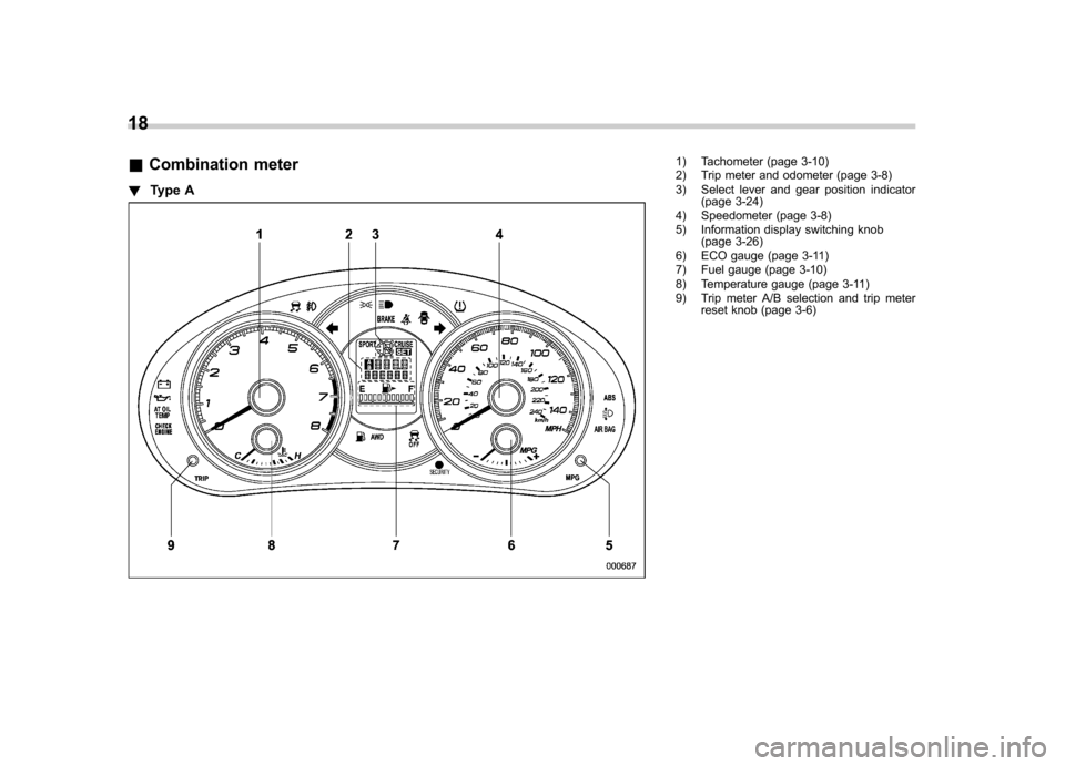
18 &Combination meter
! Type A
1) Tachometer (page 3-10)
2) Trip meter and odometer (page 3-8)
3) Select lever and gear position indicator
(page 3-24)
4) Speedometer (page 3-8)
5) Information display switching knob (page 3-26)
6) ECO gauge (page 3-11)
7) Fuel gauge (page 3-10)
8) Temperature gauge (page 3-11)
9) Trip meter A/B selection and trip meter reset knob (page 3-6)
Page 22 of 436

!Type B (U.S.-spec. models)1) Tachometer (page 3-10)
2) Speedometer (page 3-8)
3) Fuel gauge (page 3-10)
4) Trip meter A/B selection and trip meter
reset knob (page 3-6)
5) Odometer/Trip meter (page 3-8)
6) Select lever and gear position indicator (AT models) (page 3-24)
7) Coolant temperature low indicator light/ Coolant temperature high warning light
(page 3-16) 19
– CONTINUED –
Page 23 of 436

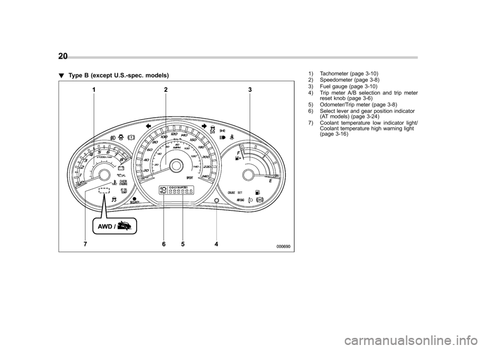
20 !Type B (except U.S.-spec. models)
1) Tachometer (page 3-10)
2) Speedometer (page 3-8)
3) Fuel gauge (page 3-10)
4) Trip meter A/B selection and trip meter
reset knob (page 3-6)
5) Odometer/Trip meter (page 3-8)
6) Select lever and gear position indicator (AT models) (page 3-24)
7) Coolant temperature low indicator light/ Coolant temperature high warning light
(page 3-16)
Page 122 of 436

(a) do not press the trip knob for 10
seconds or (b) open and close the driver’s
door, the fuel gauge indication will turn off.
NOTE
You will see the “”sign in the fuel
gauge.
This indicates that the fuel filler door
(lid) is located on the right side of thevehicle. &
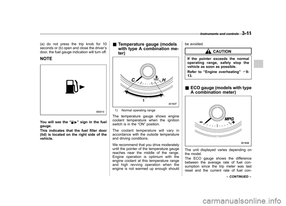
Temperature gauge (models
with type A combination me- ter)
1) Normal operating range
The temperature gauge shows engine
coolant temperature when the ignition
switch is in the “ON ”position.
The coolant temperature will vary in
accordance with the outside temperature
and driving conditions.
We recommend that you drive moderately
until the pointer of the temperature gauge
reaches near the middle of the range.
Engine operation is optimum with the
engine coolant at this temperature range
and high revving operation when the
engine is not warmed up enough should be avoided.
CAUTION
If the pointer exceeds the normal
operating range, safely stop the
vehicle as soon as possible.
Refer to “Engine overheating ”F9-
13.
& ECO gauge (models with type
A combination meter)
The unit displayed varies depending on
the model.
The ECO gauge shows the difference
between the average rate of fuel con-
sumption since the trip meter was last
reset and the current rate of fuel con- Instruments and controls
3-11
– CONTINUED –
Page 123 of 436

3-12Instruments and controls
sumption.
The ECO gauge indicates the current fuel
efficiency as shown in the following chart.
Displayed unit Needle pointing
“ + ” side “-” side
MPG Better Poorer
l/100km Poorer Better
NOTE . The ECO gauge shows only an
approximate indication of fuel effi-
ciency.. After resetting the trip meter, the
average rate of fuel consumption is not
shown until driving 0.6 mile (1 km).
Until that time, the ECO gauge does notoperate. Warning and indicator lights
Several of the warning and indicator lights
illuminate when the ignition switch is
initially turned to the
“ON ”position. This
permits checking the operation of thebulbs.
Apply the parking brake and turn the
ignition switch to the “ON ”position. For
the system check, the following lights
illuminate and turn off after several sec-
onds or after the engine has started.
: Seatbelt warning light (The seatbelt warning light turns off
only when the driver fastens theseatbelt.)
: Front passenger ’s seatbelt warning
light
(The seatbelt warning light turns off
only when the front seat passenger
fastens the seatbelt.)
: SRS airbag system warning light
ON /
: Front passenger ’s frontal airbag
ON indicator light
/: Front passenger ’s frontal airbag
OFF indicator light
: CHECK ENGINE warning light/Mal- function indicator light
: Coolant temperature high warning light
(if equipped)
: Charge warning light
: Oil pressure warning light
: AT OIL TEMP warning light (AT models)
: Low tire pressure warning light(U.S.- spec. models)
/: ABS warning light
/: Brake system warning light
: Low fuel warning light
: Hill start assist warning light (MT models)
: Door open warning light
: AWD warning light (AT models)
: Automatic headlight beam leveler warning light (models with HID head- lights)
: Vehicle Dynamics Control warninglight/Vehicle Dynamics Control opera-
tion indicator light
: Vehicle Dynamics Control OFF indica-tor light
Page 130 of 436

pressure, a tire may have signifi-
cant damage and a fast leak that
causes the tire to lose air rapidly.
If you have a flat tire, replace it
with a spare tire as soon aspossible.
. When a spare tire is mounted or a
wheel rim is replaced without the
original pressure sensor/trans-
mitter being transferred, the low
tire pressure warning light will
illuminate steadily after blinking
for approximately one minute.
This indicates the TPMS is un-
able to monitor all four road
wheels. Contact your SUBARU
dealer as soon as possible for
tire and sensor replacement and/
or system resetting.
CAUTION
. The tire pressure monitoring sys-
tem is NOT a substitute for
manually checking tire pressure.
The tire pressure should be
checked periodically (at least
monthly) using a tire gauge.
. After any change to tire pressure
(s), the tire pressure monitoring
system will not re-check tire inflation pressures until the vehi-
cle is first driven more than 20
mph (32 km/h). After adjusting
the tire pressures, increase the
vehicle speed to at least 20 mph
(32 km/h) to start the TPMS re-
checking of the tire inflation
pressures. If the tire pressures
are now above the severe low
pressure threshold, the low tire
pressure warning light should
turn off a few minutes later.
Therefore, be sure to install the
specified size for the front and
rear tires.
& ABS warning light
CAUTION
. If any of the following conditions
occur, we recommend that you
have the ABS system repaired at
the first available opportunity by
your SUBARU dealer. – The warning light does not
illuminate when the ignition
switch is turned to the “ON ”
position.
– The warning light illuminates
when the ignition switch is turned to the
“ON ”position,
but it does not turn off even
when the vehicle speed ex-
ceeds approximately 8 mph
(12 km/h).
– The warning light illuminates
during driving.
. When the warning light is on (and
the brake system warning light is
off), the ABS function shuts
down. However, the conventional
brake system continues to oper-
ate normally.
The ABS warning light illuminates to-
gether with the brake system warning light
if the EBD system malfunctions. For
further details of the EBD system mal-
function warning, refer to “Brake system
warning light ”F 3-20.
NOTE
If the warning light behaves as follows,
the ABS system may be considerednormal. . The warning light illuminates right
after the engine is started but turns off
immediately, remaining off.. The warning light remains on after
the engine has been started, but it
turns off when the vehicle speed
reaches approximately 8 mph (12 Instruments and controls
3-19
– CONTINUED –
Page 139 of 436

3-28Instruments and controls
NOTE
The indicated values vary in accor-
dance with changes in the vehicle ’s
running conditions. Also, the indicated
values may differ slightly from the
actual values and should thus be
treated only as a guide. & Average fuel consumption
1) U.S.-spec. models
2) Except U.S.-spec. models
This display shows the average rate of
fuel consumption since the trip meter was
last reset.
When either of the trip meter displays is
reset, the corresponding average fuel
consumption value is also reset. NOTE .
The indicated values vary in accor-
dance with changes in the vehicle ’s
running conditions. Also, the indicated
values may differ slightly from the
actual values and should thus be
treated only as a guide.. After either trip meter display is
reset, the average fuel consumption
corresponding to that trip meter dis-
play is not shown until the vehicle has
subsequently covered a distance of 1
mile (or 1 km). & To turn off fuel consumption
indicator display
The fuel consumption indicator display
can be turned off.
To turn off this display, turn the ignition
switch to the “LOCK ”position and press
the “+ ” button adjacent to the information
display for approximately 5 seconds. The
information display and the clock display
will blink for 3 seconds and then the fuel
consumption display will turn off.
To restore the indicator, once again pressthe “+ ” button for approximately 5 sec-
onds. NOTE . The initial display setting of the fuel
consumption indicator of your vehicle has been set to operational at the time
of shipment from the factory..
The average fuel consumption is
calculated even while the indicator is
not displayed.. Even if you turn off the fuel con-
sumption indicator, the fuel consump-
tion indicator will automatically turn on
when the battery voltage is stopped
and then reapplied due to battery
replacement or fuse replacement.
Page 144 of 436

Wiper and washer
WARNING
In freezing weather, do not use the
windshield washer until the wind-
shield is sufficiently warmed by the
defroster.
Otherwise the washer fluid can
freeze on the windshield, blocking
your view.
CAUTION
. Do not operate the washer con-
tinuously for more than 10 sec-
onds, or when the washer fluid
tank is empty. This may cause
overheating of the washer motor.
Check the washer fluid level
frequently, such as at fuel stops.
. Do not operate the wipers when
the windshield or rear window is
dry. This may scratch the glass,
damage the wiper blades and
cause the wiper motor to burn
out. Before operating the wipers
on a dry windshield or rear
window, always use the wind-
shield washer. .
In freezing weather, be sure that
the wiper blades are not frozen to
the windshield or rear window
before switching on the wipers.
Attempting to operate the wipers
with the blades frozen to the
window glass could cause not
only the wiper blades to be
damaged but also the wiper mo-
tor to burn out. If the wiper
blades are frozen to the window
glass, be sure to operate the
defroster, windshield wiper dei-
cer (if equipped) or rear window
defogger before turning on the
wiper.
. If the wipers stop during opera-
tion because of ice or some other
obstruction on the window, the
wiper motor could burn out even
if the wiper switch is turned off. If
this occurs, promptly stop the
vehicle in a safe place, turn the
ignition switch to the “LOCK ”
position and clean the window
glass to allow proper wiper op-eration.
. Use clean water if windshield
washer fluid is unavailable. In
areas where water freezes in
winter, use SUBARU Windshield
Washer Fluid or the equivalent. Refer to
“Windshield washer
fluid ”F 11-37.
Also, when driving the vehicle in
freezing temperature, use non-
freezing type wiper blades.
. Do not clean the wiper blades
with gasoline or a solvent, such
as paint thinner or benzine. This
will cause deterioration of the
wiper blades.
NOTE . The wipers operate only when the
ignition switch is in the “ON ”or “Acc ”
position. . The front wiper motor is protected
against overload by a circuit breaker. If
the motor operates continuously under
an unusually heavy load, the circuit
breaker may trip to stop the motor
temporarily. If this happens, park your
vehicle in a safe place, turn off the
wiper switch, and wait for approxi-
mately 10 minutes. The circuit breaker
will reset itself, and the wipers will
again operate normally.. Clean your wiper blades and win-
dow glass periodically with a washer
solution to prevent streaking, and to
remove accumulations of road salt or
road film. Operate the windshield Instruments and controls
3-33
– CONTINUED –