Page 647 of 751

12-18
Air Bleeding ▶
Lift up the vehicle very carefully.
Turn the steering wheel to its both ends
several times and add the oil up to MAX line
in the steering oil reservoir.
Periodically crank the starting motor and turn
the steering wheel to its both ends without
any interruption.
Check the oil level again. If the oil level is
fluctuated, repeat the procedures from step 3
to step 5.
Start the engine.
Turn the steering wheel to its both ends until
any bubble can be found in the steering oil
reservoir.
Perform the test drive and check the steering
wheel for normal operation and noise.
If the oil level abruptly goes up, bleed the air
from the system again. 1.
2.
3.
4.
5.
6.
7.
8.
The air bleeding should be done after servicing
the power steering system and when the
difference between two measurements (cooled
and normal temperature) is prominent.
Max
Min
Normal Abnormal
If the air bleeding is not properly performed,
the life span of the power steering pump
may be shortened. -
Page 648 of 751
12-194610-01
Oil Pump Pressure Check ▶
Unscrew the pressure line fitting in power
steering pump.
Install the pressure gauge between the
power steering pump and the power steering
oil pressure line.
Place the shift lever to neutral position. Apply
the parking brake.
Open the valve in pressure gauge. Start the
engine and let it run at idle speed.
Turn the steering wheel several times so that
the oil temperature reaches to normal
operating level. 1.
2.
3.
4.
5.
Before checking the pressure, check the oil
level and belt tension. Prepare the empty
container to collect the spilled oil during the
service. Check the oil pump pressure to locate any
defect in oil pump.
Fully close the valve in pressure gauge and
measure the oil pressure. 6.
Relief pressure
90 ± 3 bar
Oil pump
Steering gear box
To prevent internal damage, do not close
the gauge valve over 10 seconds.
Keep the oil temperature at proper range. -
-
Page 649 of 751
12-20
Measure the oil pressure with the gauge valve
fully open. 7.
Pressure at no load
3 to 5 bar
If the pump pressure is in specified range, the
pump is normal. If not, replace the power
steering pump 8.
Turn the steering wheel right or left until it
stops with the engine idling and valve fully
open. 9.
Oil pressure78 to 83 bar
To prevent the internal damage, do not close
the gauge valve for over 10 seconds.
Keep the oil temperature at proper range. -
-
Page 650 of 751

12-214610-01
1. SYSTEM DESCRIPTION
The power steering has been designed to make the wheel move more easily than in a manual steering
system. The hydraulic power assists the process utilizing hydraulic fluid. The fluid increases pressure in
the power steering pump and aids the movement of the steering mechanism. The power steering
system consists of pump, oil reservoir, rack and gear box. The power steering pump is a vane type and
delivers hydraulic pressure to operate the power steering system. The pressure relief valve in the pump
controls the discharging pressure. The rotary valve in the rack and the pinion gear directs the oil from the
power steering pump to one side of the rack piston. The integrated rack piston converts the hydraulic
pressure to linear movement. The operating force of the rack moves the wheels through the tie rod, the
tie rod end and the steering knuckle. Even though the hydraulic pressure cannot be generated, a driver
can steer the vehicle without power assist but it needs very high steering force. In this case, the
operating force of the steering wheel is conveyed to the pinion, and the movement of the pinion moves
the rack through the pinion gear combined to the rack gear.
Page 651 of 751
12-22
2. SYSTEM LAYOUT
The steering pump is driven by the engine power through a belt. This pump circulates the power steering
oil from the reservoir -> steering pump -> oil supply pipe -> steering gear box -> oil return pipe ->
reservoir to perform steering operations
Return hose & tube
Steering pump &
reservoir
High pressure hose
Linkage gear box Steering wheel
Lower shaft Column & shaft
Return hose & tube
Steering pump &
reservoir
High pressure hose
Linkage gear box Steering wheel
Lower shaft Column & shaft
HPS model
SSPS model
Page 659 of 751

13-94620-01
▶Components
PCV (Pressure Control Valve)
This valve controls the hydraulic pressure supplied to reaction device by moving the spool valve
according to the changes of solenoid valve.
Reaction device
This device increases the steerability effect by binding the input shaft with supplied hydraulic pressure
from PCV.
Solenoid valve
This valve determines the valve spool position in PCV with the electric current supplied from ECPS
control unit. 1.
2.
3.
3) Operation of Solenoid Valve
SSPS control unit controls the current to solenoid valve according to the vehicle speed. Based on this
current, the solenoid valve changes the position of valve spool to control the hydraulic pressure to the
reaction plunger. Accordingly, the SSPS system can get the desired steering force according to the
vehicle speed.
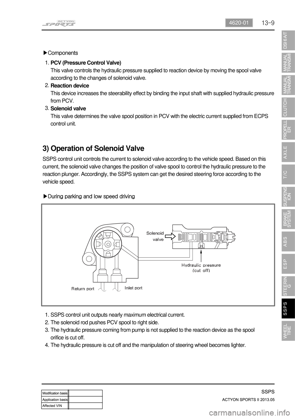
▶During parking and low speed driving
SSPS control unit outputs nearly maximum electrical current.
The solenoid rod pushes PCV spool to right side.
The hydraulic pressure coming from pump is not supplied to the reaction device as the spool
orifice is cut off.
The hydraulic pressure is cut off and the manipulation of steering wheel becomes lighter. 1.
2.
3.
4.
Page 668 of 751

14-74170-09
2) Typical Inspection
Tread
Inspect the tread condition on the tire surface
and various damages resulting from the
foreign materials, crack, stone or nail etc. If
there is any damage in the tire, repair or
replace it. 1.
Wear limit 2.
Measure the depth of the tire tread. If the
depth of the tread is below the specified
value, replace the tire -
You can see the protruded part in the
groove at the point with mark "▲", which
is the indicator of the tread wear limit.
The limit of the tread wear for all season
tires are 1.6 mm, which is the same as the
general tires, but the wear limit mark is
indicated as '↓'. -
-
Wear limit 1.6 mm
Higher than recommended pressure can cause hard ride, tire bruising or damage and rapid tread
wear at the center of the tire.
Excessive tire wear over the limit of the tread wear (1.6 mm) can cause lower sliding friction due to
longer braking distance, easy tire burst by foreign materials, tire hydroplaning, and tough brake and
steering wheel handling. -
-
Page 679 of 751

14-18
4. WHEEL ALIGNMENT
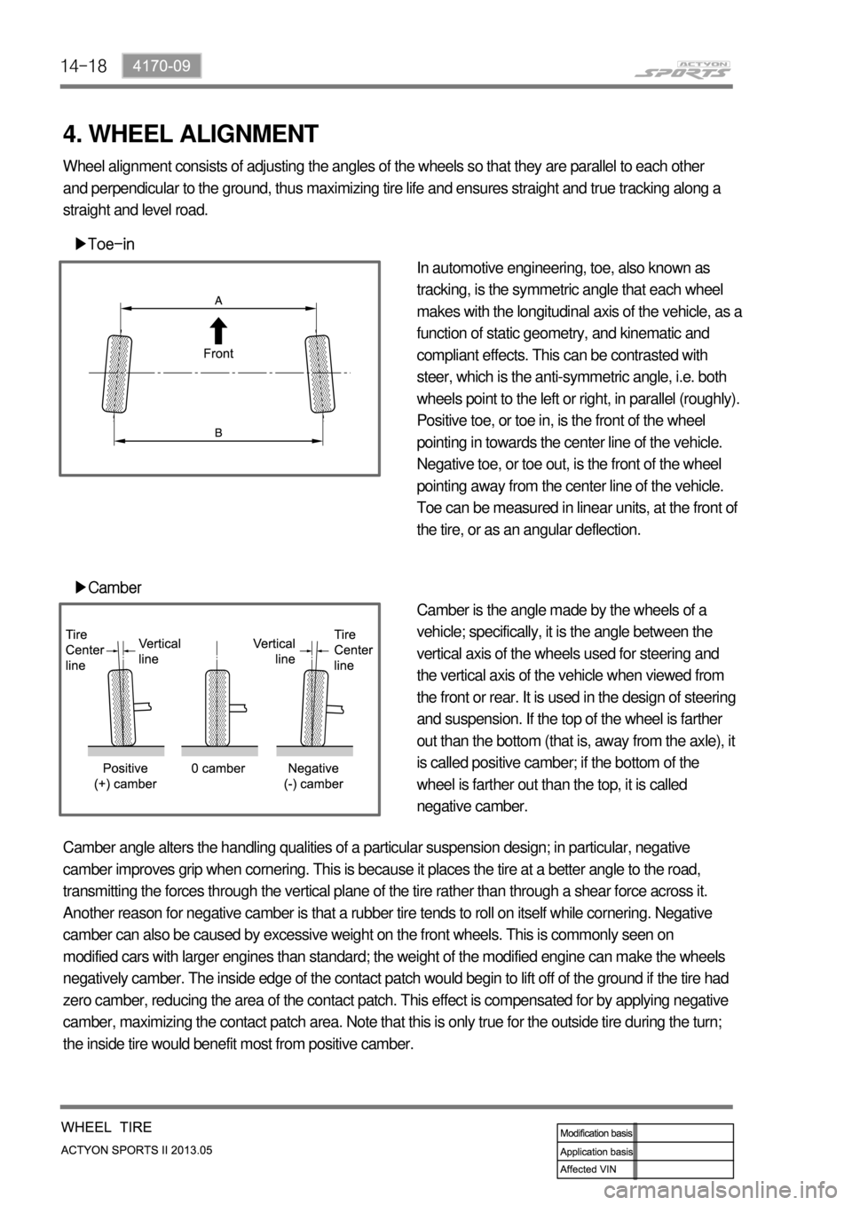
▶Toe-in
▶Camber
In automotive engineering, toe, also known as
tracking, is the symmetric angle that each wheel
makes with the longitudinal axis of the vehicle, as a
function of static geometry, and kinematic and
compliant effects. This can be contrasted with
steer, which is the anti-symmetric angle, i.e. both
wheels point to the left or right, in parallel (roughly).
Positive toe, or toe in, is the front of the wheel
pointing in towards the center line of the vehicle.
Negative toe, or toe out, is the front of the wheel
pointing away from the center line of the vehicle.
Toe can be measured in linear units, at the front of
the tire, or as an angular deflection.
Camber is the angle made by the wheels of a
vehicle; specifically, it is the angle between the
vertical axis of the wheels used for steering and
the vertical axis of the vehicle when viewed from
the front or rear. It is used in the design of steering
and suspension. If the top of the wheel is farther
out than the bottom (that is, away from the axle), it
is called positive camber; if the bottom of the
wheel is farther out than the top, it is called
negative camber. Wheel alignment consists of adjusting the angles of the wheels so that they are parallel to each other
and perpendicular to the ground, thus maximizing tire life and ensures straight and true tracking along a
straight and level road.
Camber angle alters the handling qualities of a particular suspension design; in particular, negative
camber improves grip when cornering. This is because it places the tire at a better angle to the road,
transmitting the forces through the vertical plane of the tire rather than through a shear force across it.
Another reason for negative camber is that a rubber tire tends to roll on itself while cornering. Negative
camber can also be caused by excessive weight on the front wheels. This is commonly seen on
modified cars with larger engines than standard; the weight of the modified engine can make the wheels
negatively camber. The inside edge of the contact patch would begin to lift off of the ground if the tire had
zero camber, reducing the area of the contact patch. This effect is compensated for by applying negative
camber, maximizing the contact patch area. Note that this is only true for the outside tire during the turn;
the inside tire would benefit most from positive camber.