Page 206 of 751
15-6
Glow plug
Differential pressure
sensorCamshaft position
sensor
1. MAJOR COMPONENTS
Rear EGT sensor
Oxygen sensor
Front EGT sensor
HFM (air mass/
temperature)
Injector (C3I)
Variable swirl valve
actuator
IMV
Page 209 of 751
15-90000-00
Fuel rail pressure
sensor
(2) Components for ECU Input
CAN
- ABS & ESP
- GCU
- Instrument
cluster
- TCUSwirl valve
position sensor
Differential
pressure sensorE-EGR valve
position sensorCamshaft position
sensorCoolant
temperature
sensor
Exhaust gas
temperature
sensorHFM sensorOxygen sensorT-MAP sensor
Crankshaft
position sensorAccelerator pedal
sensorThrottle position
sensorKnock sensor
-Auto cruise switch
- Rear right wheel
speed (without ABS)
- Refrigerant pressure
sensor
- Clutch pedal signal
- Blower switch signal
- Brake pedal signal
Water sensor
Page 247 of 751
15-470000-00
(15) CDPF control
A. Overview
As the solution for environmental regulations and PM Particle Material) of diesel engine, the low emission
vehicle is getting popular. This vehicle is equipped with an extra filter to collect the soot and burn it again
so that the amount of PM in the exhaust gas passed through the DOC (Diesel Oxidation Catalyst) is
reduced. The CDPF (Catalyst & Diesel Particulate Filter) is an integrated filter including DOC (Diesel
Oxidation Catalyst) and DPF (Diesel Particulate Filter).
For details, refer to Chapter "CDPF".
B. Components
Oxygen
sensorFront
EGT sensorCDPF
(DOC + DPF)Rear
EGT sensor
Differential pressure
sensorD20DTR ECUElectric throttle body
Page 249 of 751

15-490000-00
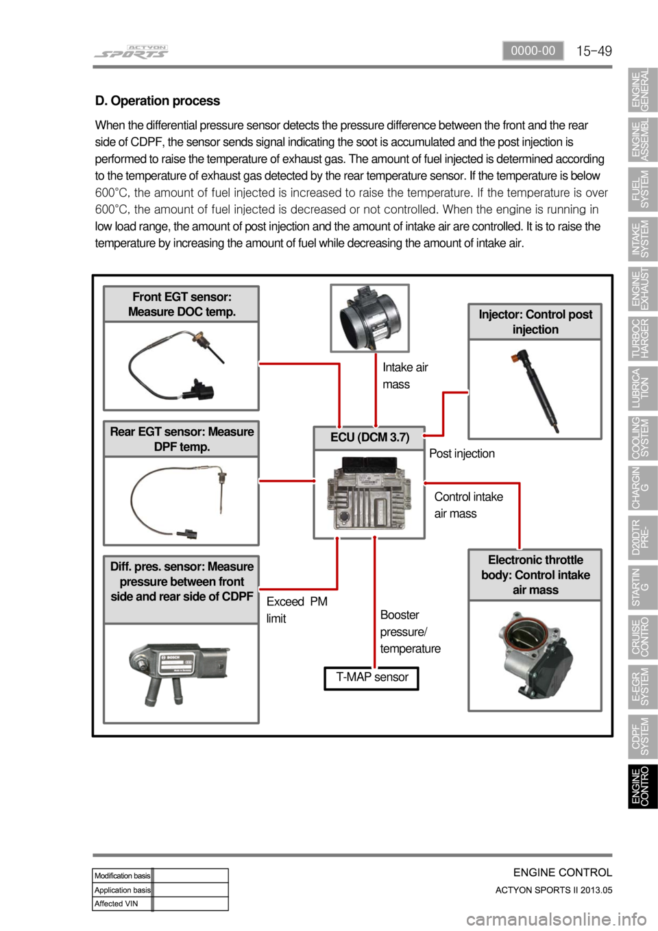
Diff. pres. sensor: Measure
pressure between front
side and rear side of CDPF
ECU (DCM 3.7)
Injector: Control post
injection
D. Operation process
When the differential pressure sensor detects the pressure difference between the front and the rear
side of CDPF, the sensor sends signal indicating the soot is accumulated and the post injection is
performed to raise the temperature of exhaust gas. The amount of fuel injected is determined according
to the temperature of exhaust gas detected by the rear temperature sensor. If the temperature is below
600°C, the amount of fuel injected is increased to raise the tem
perature. If the temperature is over
600°C, the amount of fuel injected is decreased or not controlled. When the engine is running in
low load range, the amount of post injection and the amount of intake air are controlled. It is to raise the
temperature by increasing the amount of fuel while decreasing the amount of intake air.
Front EGT sensor:
Measure DOC temp.
Rear EGT sensor: Measure
DPF temp.
Electronic throttle
body: Control intake
air mass
T-MAP sensor
Intake air
mass
Exceed PM
limitBooster
pressure/
temperaturePost injection
Control intake
air mass
Page 274 of 751

02-52211-06
1. FUEL SYSTEM
The function of the fuel metering system is to deliver the correct amount of fuel to the engine under all
operating conditions.
The fuel is delivered to the engine by the individual fuel injectors mounted into the intake manifold nea
r
each cylinder.
The main fuel control sensors are the Mass Air Flow (MAF) sensor and the oxygen (O2) sensors.
The MAF sensor monitors the mass flow of the air being drawn into the engine. An electrically heated
element is mounted in the intake air stream, where it is cooled by the flow of incoming air. Engine Control
Module (ECM) modulates the flow of heating current to maintain the temperature differential between the
heated film and the intake air at a constant level. The amount of heating current required to maintain the
temperature thus provides an index for the mass air flow. This
concept automatically compensates for variations in air density, as this is one of the factors that
determines the amount of warmth that the surrounding air absorbs from the heated element. MAF
sensor is located between the air filter and the throttle valve.
Under high fuel demands, the MAF sensor reads a high mass flow condition, such as wide open throttle.
The ECM uses this information to enrich the mixture, thus increasing the fuel injector on-time, to provide
the correct amount of fuel. When decelerating, the mass flow decreases. This mass flow change is
sensed by the MAF sensor and read by the ECM, which then decreases the fuel injector on-time due to
the low fuel demand conditions.
The O2 sensors are located in the exhaust pipe before catalytic converter. The O2 sensors indicate to
the ECM the amount of oxygen in the exhaust gas, and the ECM changes the air/fuel ratio to the engine
by controlling the fuel injectors. The best air/fuel ratio to minimize exhaust emissions is 14.7 to 1, which
allows the catalytic converter to operate most efficiently. Because
of the constant measuring and adjusting of the air/fuel ratio, the fuel injection system is called a "closed
loop" system.
The ECM uses voltage inputs from several sensors to determine how much fuel to provide to the engine.
The fuel is delivered under one of several conditions, called "modes".
Page 526 of 751
05-4
1. OVERVIEW
The propeller shaft transfers the power through the transmission and transfer case to the front/rear axle
differential carrier (final reduction gear).
It is manufactured by a thin rounded steel pipe to have the strong resisting force against the torsion and
bending.
Both ends of propeller shaft are connected to the spider and the center of propeller shaft is connected to
the spline to accommodate the changes of the height and length.
The rubber bushing that covers the intermediate bearing keeps the balance of rear propeller shaft and
absorbs its vibration.
Function of propeller shaft ▶
Transmits driving torque.
Compensates the angle change (universal joint / CV joint).
Compensates the axial length change (splines for the slip joint). -
-
-
Front propeller shaft
Rear propeller shaft
Page 553 of 751

09-4
2. SYSTEM OVERVIEW
1) Terms and Definition
CBS: Conventional Brake System
ABS: Anti-Lock Brake System
EBD: Electronic brake-Force Distribution
ESP: Electronic Stability Program
ABD: Automatic Braking Differential
ASR: Acceleration Slip Regulation
AYC: Active Yaw Control (Understeer and Oversteer Control)
HBA: Hydraulic Brake Assistant
ARP: Active Rollover Protection
HSA: Hill Start Assistant
Brake pad: Brake pad is a component of disk brakes used in automotive and other applications.
Brake pad is steel backing plates with friction material bound to the surface that faces the brake disc.
Brake disc: The brake disc is a device for slowing or stopping the rotation of a wheel while it is in
motion.
Brake caliper: To stop the wheel, friction material in the form of brake pads (mounted on a device
called a brake caliper) is forced hydraulically against both sides of the disc. Friction causes the disc
and attached wheel to slow or stop.
Brake master cylinder: The brake master cylinder is a control device that converts non-hydraulic
pressure (commonly from a driver's foot) into hydraulic pressure, in order to move other device(s)
which are located at the other end of the hydraulic system, such as one or more slave cylinders. As
piston(s) move along the bore of the master cylinder, this movement is transferred through the
hydraulic fluid, to result in a movement of the slave cylinder(s). The hydraulic pressure created by
moving a piston (inside the bore of the master cylinder) toward the slave cylinder(s) compresses the
fluid evenly, but by varying the comparative surface-area of the master cylinder and/or each slave
cylinder, one will vary the amount of force and displacement applied to each slave cylinder (relative to
the amount of force and displacement that was applied to the master cylinder). -
-
-
-
-
-
-
-
-
-
-
-
-
-
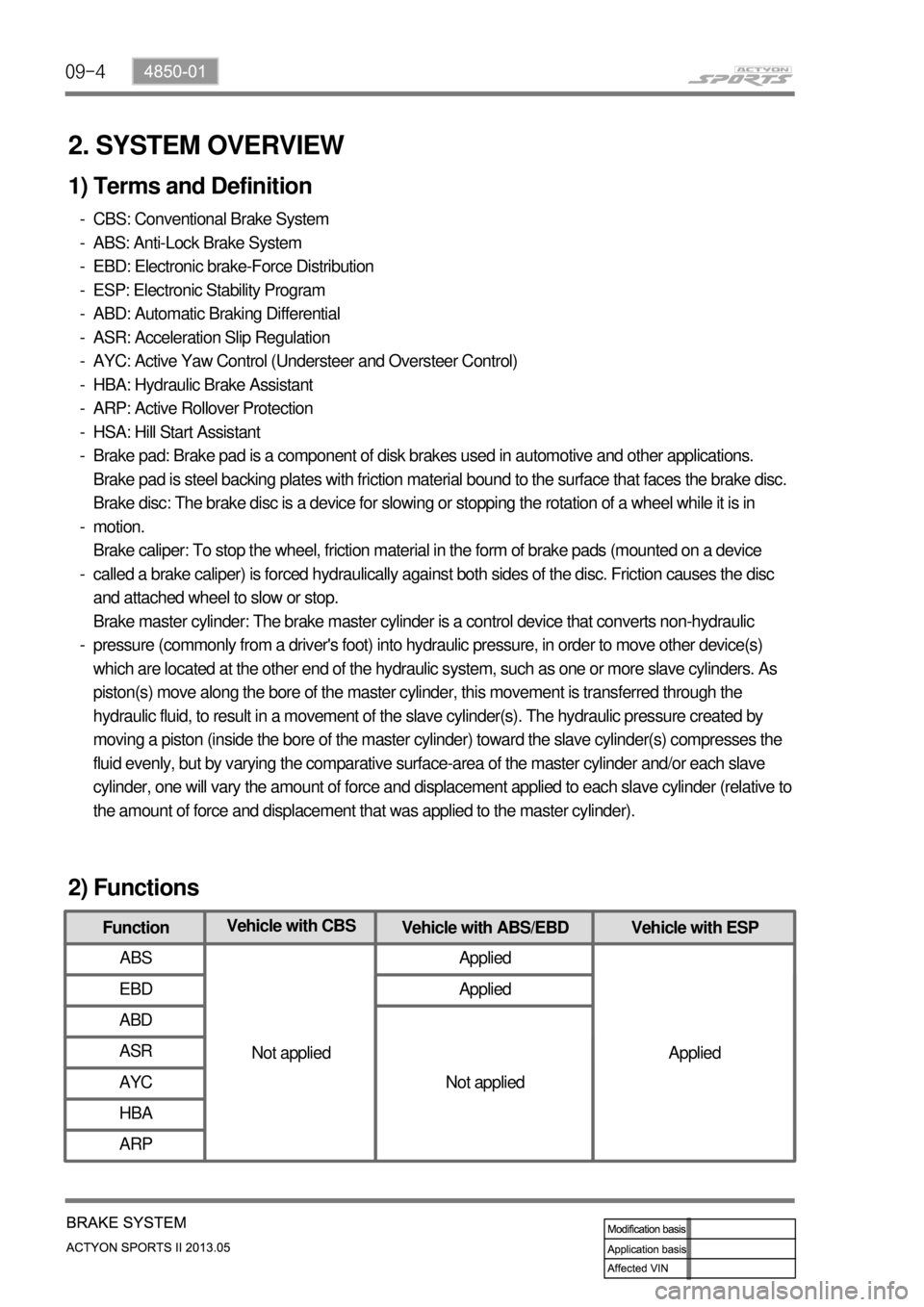
FunctionVehicle with CBS
Vehicle with ABS/EBD Vehicle with ESP
ABS
Not appliedApplied
Applied EBD Applied
ABD
Not applied ASR
AYC
HBA
ARP
2) Functions