Page 597 of 751
10-174892-01
3) Basic ABS Control
Operation of ABS control unit ▶
Applications of the ABS control unit The signals
produced by the wheel sensors are evaluated
in the electronic control unit. From the
information received, the control unit must first
compute the following variables:
Wheel speed
Reference speed
Deceleration
Slip -
-
-
-
Reference speed ▶
The reference speed is the mean, I.e. average speed of all wheel speeds determined by simple
approximation.
Simplified ABS control ▶
If, during braking, one wheel speed deviates from the reference speed, the ABS control unit attempts to
correct that wheel speed by modulating the brake pressure until it again matches the reference speed.
When all four wheels tend to lock, all four wheels speeds suddenly deviate from the previously
determined reference speed. In that case, the control cycle is initiated again in order to again correct the
wheel speed by modulating the brake pressure.
Page 599 of 751

10-194892-01
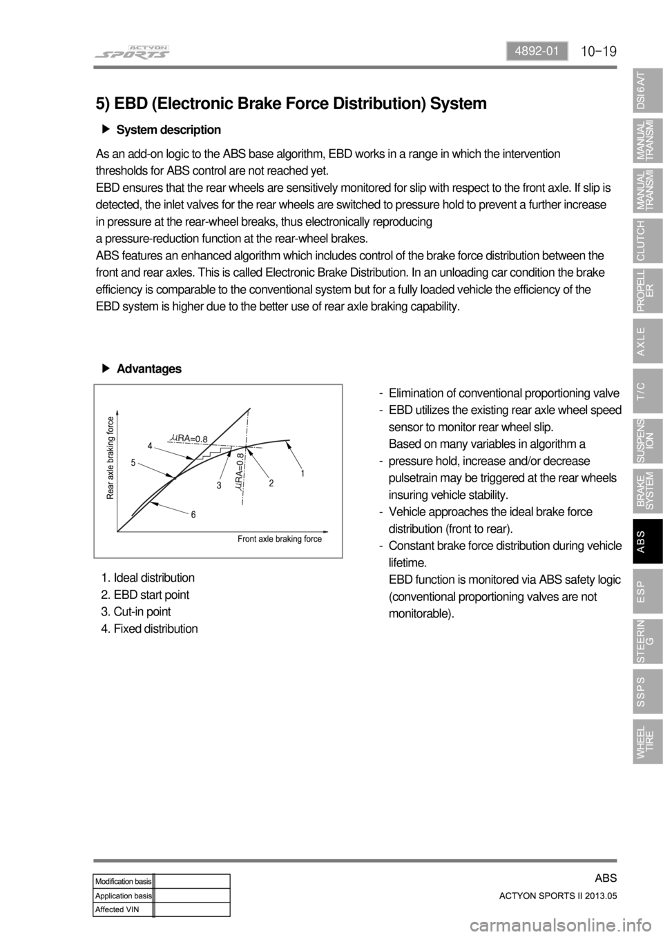
5) EBD (Electronic Brake Force Distribution) System
System description ▶
As an add-on logic to the ABS base algorithm, EBD works in a range in which the intervention
thresholds for ABS control are not reached yet.
EBD ensures that the rear wheels are sensitively monitored for slip with respect to the front axle. If slip is
detected, the inlet valves for the rear wheels are switched to pressure hold to prevent a further increase
in pressure at the rear-wheel breaks, thus electronically reproducing
a pressure-reduction function at the rear-wheel brakes.
ABS features an enhanced algorithm which includes control of the brake force distribution between the
front and rear axles. This is called Electronic Brake Distribution. In an unloading car condition the brake
efficiency is comparable to the conventional system but for a fully loaded vehicle the efficiency of the
EBD system is higher due to the better use of rear axle braking capability.
Advantages ▶
Elimination of conventional proportioning valve
EBD utilizes the existing rear axle wheel speed
sensor to monitor rear wheel slip.
Based on many variables in algorithm a
pressure hold, increase and/or decrease
pulsetrain may be triggered at the rear wheels
insuring vehicle stability.
Vehicle approaches the ideal brake force
distribution (front to rear).
Constant brake force distribution during vehicle
lifetime.
EBD function is monitored via ABS safety logic
(conventional proportioning valves are not
monitorable). -
-
-
-
-
Ideal distribution
EBD start point
Cut-in point
Fixed distribution 1.
2.
3.
4.
Page 605 of 751
11-34890-10
1. SPECIFICATION
1) Specification of Active Wheel Sensor
Description Specification Remark
Supplying voltage 4.5 ~ 16.0V
Output current (at 2.75 km/h of vehicle
speed)7mA(Lo) ~ 14mA(Hi)
Tightening torqueFront: 7.8 to 11.8 Nm
Rear: 7.8 to 11.8 Nm
Operating temperature-40 ~ 150℃
Operating frequency 1 ~ 2,500Hz
UnitDescription
Specification
ABS ESP
HECU Clock frequency: 32 MHz Clock frequency: 50 MHz
Memory: 128 KB Memory: 256 KB
Wheel speed
sensorActive type Active type Output: 7~14 mA
Steering wheel
angle sensorNone Max. detection angle speed:
1500 °/SecPulse duty:
50±10%
Operating voltage: 9 to 12 V
Sensor cluster None Yaw rate sensor + lateral G
sensor + longitudinal G sensor
(4WD)Mounting
direction should
be kept (CAN
communcation)
Longitudinal G
sensor4WD only None
Pressure sensor None HECU integrated
Page 606 of 751
11-4
2) Specification of Steering Wheel Angle Sensor
3) Specification of Sensor Cluster
Description Specification
Operating voltage 9 to 16 V
Maximum output current 10 mA
Maximum detection angle speed±100°/Sec
Operating temperature-30 to 75 ℃
Supplying voltage 9 to 16 V (battery voltage)
Output voltage (HI) approx. 3.50 V (3.0 to 4.1 V)
Output voltage (LO) approx. 1.50 V (1.3 to 2.0 V)
Pulses/rev 45 pulses/rev
Description Specification
Supplying voltage approx. 12 V (8 to 16 V)
Current consumption below 250 mA -
Operating range Yaw rate sensor± 75 °/Sec
Lateral/longitudinal sensor± 14.7m/Sec²
Page 607 of 751
11-54890-10
2. MAJOR CHANGES
Steering wheel angle sensor
<00540047007a009b008c008c009900900095008e0047009e008f008c008c0093004700880095008e0093008c0047009a008c0095009a0096009902c5009a0047008800970097008c0088009900880095008a008c004700880095008b0047009e0090009900
900095008e004700990096009c009b008c0047008a008f0088>nged
Page 608 of 751
11-6
3. SYSTEM LAYOUT
ESP System ▶
Sensor - front wheel speed
Sensor - rear wheel speed
Screw (7.8~11.8 Nm)
Clip - cable holder
Clip - sensor cable mounting rear
Plug - blind
HECU
Sensor - cluster
Nut (9.8~10.8 Nm)
ESP OFF switch
Steering wheel sensor 1.
2.
3.
4.
5.
6.
9.
10.
11.
12.
13.
Page 610 of 751
11-8
1. OVERVIEW
The ESP (Electronic Stability Program) has been developed to help a driver avoid danger of losing
control of the vehicle stability due to understeer or oversteer during cornering. The yaw rate sensor,
lateral sensor and longitudinal sensor in the sensor cluster and the steering wheel angle sensor under
the steering column detect the vehicle conditions when the inner or outer wheels are spinning during
oversteer, understeer or cornering. The ESP ECU controls against oversteer or understeer during
cornering by controlling the vehicle stability using input values from these sensors and applying the
braking force to the corresponding wheels independently. The system also controls the engine power
right before the wheel spin synchronized to decelerate the vehicle automatically in order to maintain the
vehicle stable during cornering.
Page 611 of 751
11-94890-10
ESP OFF switch
Located on the left side of
instrument panel.
Rear wheel speed sensor
Located on the both ends of
rear axle.Front wheel speed sensor
Located on the hub assembly.Sensor cluster
Located at the bottom of center
fascia panel.
Steering wheel angle sensor
Located on column shaft with
contact coil.HECU assembly
Located near the brake booster
in engine compartment and
contains the pressure sensor.
2. COMPONENTS