Page 95 of 751

03-18
3. CAUTIONS FOR DI ENGINE
1) Cautions for DI Engine
This chapter describes the cautions for DI engine equipped vehicle. This includes the water separation
from engine, warning lights, symptoms when engine malfunctioning, causes and actions.
DI Engine 1.
Comparatively conventional diesel engines, DI engine controls the fuel injection and timing electrically,
delivers high power and reduces less emission..
System Safety Mode 2.
When a severe failure has been occurred in a vehicle, the system safety mode is activated to protect the
system. It reduces the driving force, restricts the engine speed (rpm) and stops engine operation. Refer
to "Diagnosis" section in this manual.
Engine CHECK Warning Lamp 3.
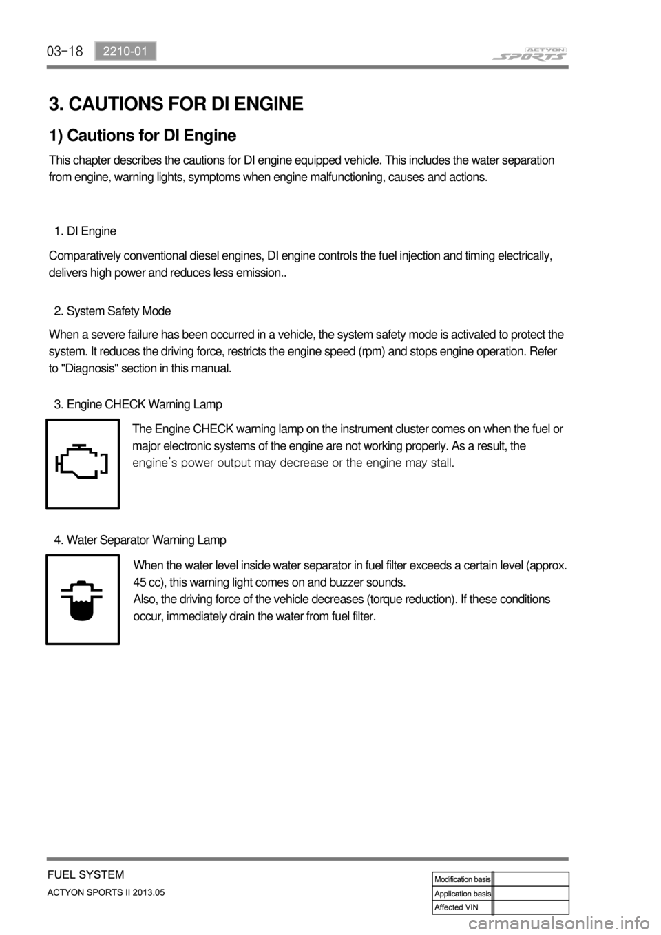
The Engine CHECK warning lamp on the instrument cluster comes on when the fuel or
major electronic systems of the engine are not working properly. As a result, the
<008c0095008e00900095008c02c5009a004700970096009e008c009900470096009c009b0097009c009b00470094008800a00047008b008c008a0099008c0088009a008c0047009600990047009b008f008c0047008c0095008e00900095008c0047009400
8800a00047009a009b0088009300930055>
Water Separator Warning Lamp 4.
When the water level inside water separator in fuel filter exceeds a certain level (approx.
45 cc), this warning light comes on and buzzer sounds.
Also, the driving force of the vehicle decreases (torque reduction). If these conditions
occur, immediately drain the water from fuel filter.
Page 97 of 751

03-20
(2) Di engine and its expected problems and remedies can be caused by
water in fuel
System supplement against paraffin separation ▶
In case of Diesel fuel, paraffin, one of the elements, can be separated from fuel during winter and then
can stick on the fuel filter blocking fuel flow and causing difficult starting finally. Oil companies supply
summer fuel and winter fuel by differentiating mixing ratio of kerosene and other elements by region and
season. However, above phenomenon can be happened if stations have poor facilities or sell improper
fuel for the season. In case of DI engine, purity of fuel is very important factor to keep internal
preciseness of HP pump and injector.
Accordingly, more dense mesh than conventional fuel filter is used. To prevent fuel filter internal clogging
due to paraffin separation, SYMC is using fuel line that high pressure and temperature fuel injected by
injector returns through fuel filter to have an effect of built-in heater (see fuel system).
System supplement and remedy against water in fuel ▶
As mentioned above, some gas stations supply fuel with excessive than specified water. In the
conventional IDI engine, excessive water in the fuel only causes dropping engine power or engine
hunting. However, fuel system in the DI engine consists of precise components so water in the fuel can
cause malfunctions of HP pump due to poor lubrication of pump caused by poor coating film during high
speed pumping and bacterization (under long period parking). To prevent problems can be caused by
excessive water in fuel, water separator is installed inside of fuel filter. When fuel is passing filter, water
that has relatively bigger specific gravity is accumulated on the bottom of the filter.
Water drain from water separator ▶
If water in the separator on the fuel filter exceeds a certain level, it will be supplied to HP pump with fuel,
so the engine ECU turns on warning lamp on the meter cluster and buzzer if water level is higher than a
certain level.
Due to engine layout, a customer cannot easily drain water from fuel filter directly, so if a customer
checks in to change engine oil, be sure to perform water drain from fuel filter.
Water
separator
To separate the water from the fuel filter,
remove the fuel filter assembly first.
Page 139 of 751
07-51543-00
1. SYSTEM DESCRIPTION
1) Overview
The lubrication system supplies oil to each lubrication section to prevent friction and wear and to remove
heat from the friction part. As the engine runs, frictional heat is generated on each lubrication section. If
this condition persists, the bearing can be burned and stuck.
In other words, it creates an oil film on each sliding surface to convert solid friction to liquid friction in order
to minimize wear and prevent temperature increasing on the friction part.
For the D20DTF engine with no oil pressure switch, the engine ECU receives the low engine oil level
signal from the oil level sensor and communicates with the instrument cluster through the CAN
communication to turn on the warning lamp.
2) Components
Oil coolerOil dipstick gaugeOil pump
Oil filter moduleOil pressure switchOil pan
Page 150 of 751

09-51451-01
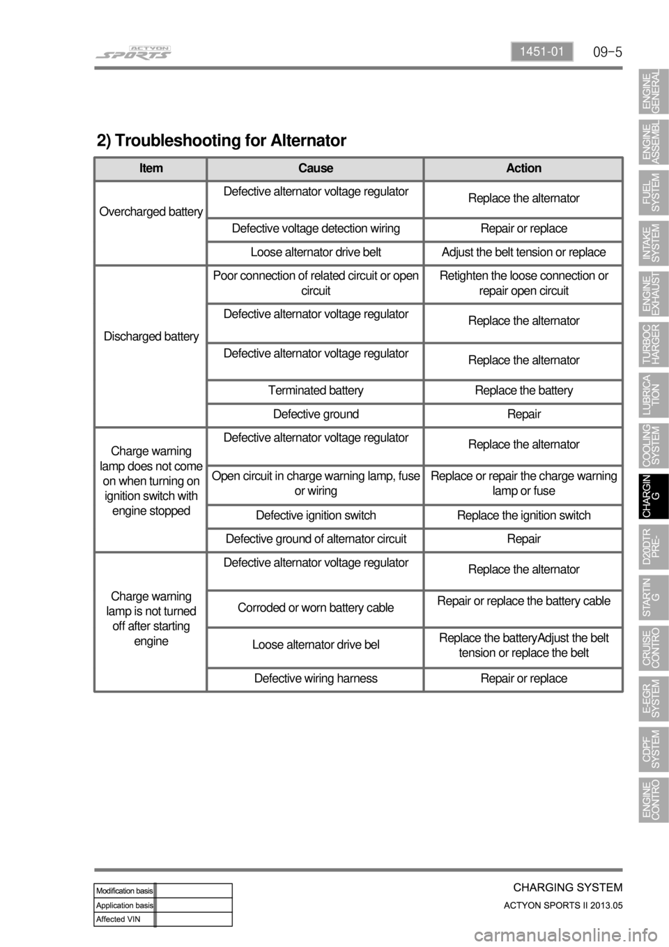
2) Troubleshooting for Alternator
Item Cause Action
Overcharged batteryDefective alternator voltage regulator
Replace the alternator
Defective voltage detection wiring Repair or replace
Loose alternator drive belt Adjust the belt tension or replace
Discharged batteryPoor connection of related circuit or open
circuitRetighten the loose connection or
repair open circuit
Defective alternator voltage regulator
Replace the alternator
Defective alternator voltage regulator
Replace the alternator
Terminated battery Replace the battery
Defective ground Repair
Charge warning
lamp does not come
on when turning on
ignition switch with
engine stoppedDefective alternator voltage regulator
Replace the alternator
Open circuit in charge warning lamp, fuse
or wiringReplace or repair the charge warning
lamp or fuse
Defective ignition switch Replace the ignition switch
Defective ground of alternator circuit Repair
Charge warning
lamp is not turned
off after starting
engineDefective alternator voltage regulator
Replace the alternator
Corroded or worn battery cableRepair or replace the battery cable
Loose alternator drive belReplace the batteryAdjust the belt
tension or replace the belt
Defective wiring harness Repair or replace
Page 154 of 751
09-91451-01
If the charge warning lamp ( ) on the instrument cluster comes on while driving, there is a
malfunction in the charge system including the battery. Therefore, carrying out the system check is
needed.
(4) Maintenance
Make sure that the battery cables are firmly connected.
If the terminals are corroded, clean them with a wire brush or sandpapers.
Always disconnect the battery cables with the ignition key removed. When disconnecting the battery
cables with the ignition key turned to ON or ACC position, several electric units can be damaged
due to sudden voltage change.
Check the battery for crack, damage or fluid leaks. Replace it if necessary.
Wipe out the battery fluid on the battery surface using a rubber glove and a clean cloth wetted with
soapy water. -
-
-
-
Page 188 of 751
14-4
2. CAUTIONS
1) Standard pattern of soot accumulation
Abnormal Soot Accumulation ▶
Normal Soot Combustion ▶
Cautions to protect the catalyst filter ▶
Use the designated fuel only.
Observe the recommended service intervals of engine oil.
Check the engine oil level frequently and add if necessary.
Do not idle the vehicle unnecessarily.
Do not turn off the engine while the vehicle is running.
Do not shift the gear selector lever to neutral when going downhill.
Do not use improper engine oil or fuel additives.
Do not drive for a long time when the warning lamp is illuminated.
Make sure no flammable material, such as dry grass or tissue paper, contacts with the catalyst filter
while the vehicle is parked.
For the vehicles used in urban traffic, driving on the expressways for more than 1 hour at least once
per week is needed so that the PM inside CDPF isn't collected to one side only. -
-
-
-
-
-
-
-
-
-
Page 189 of 751

14-52412-02
The CDPF system enters the regeneration mode
when the driving distance becomes approx. 600
to 1,200 km (may differ by the driving condition
and driving style). Then, the engine ECU
performs the CDPF regeneration operation.
However, the driver is not informed with this
operation by any engine warning lamp or vehicle
signal, so he/she may not detect this operation.
The control logic at the post-injection dur-ing the
regeneration process is to increase the fuel
injection volume and control the intake air volume
(by the throttle body) in order to increase the
temperature of the exhaust gas. The driver may
not feel any particular difference from the vehicle.
Overload of CDPF (warning lamp blinking)
2) Warning Lamp Related to CDPF
CDPF regeneration process (warning lamp NOT illuminated) ▶
If the CDPF cannot reach the regeneration temperature due to low speed driving or other reason
during the regeneration process, the soot is continuously accumulated in the CDPF. When this
condition continues and the CDPF is overloaded with soot, the engine warning lamp blinks to inform
this situation to the driver.
In order to solve this problem, drive the vehicle at a speed of approx. 80 km/h for 15 to 20 minutes to
perform the CDPF regeneration process.
If the engine warning lamp on the instrument cluster blinks, the CDPF is overloaded. In this case,
perform the step 2. 1.
2.
3.
Page 190 of 751
14-6
Excessive overload of CDPF (warning lamp illuminated)
If the vehicle is driven at a speed of 5 to 10 km/h for an extended period of time, the soot
accumulated in the CDPF cannot be burned as the CDPF cannot reach the regeneration
temperature. Then, an excessive amount of soot can be accumulated in the CDPF.
This case is much worse than the simple over-load of the CDPF. To inform this to the driver, the
engine warning lamp comes on and the engine power is decreased to protect the system.
To solve this problem, blow soot between the engine and exhaust system several times and erase
the related DTC. Then, check if the same DTC is regenerated again. If so, check the DTC related to
the differential pressure sensor. 1.
2.
3.