Page 1003 of 1336
3680-01
1. GENERAL INFORMATION
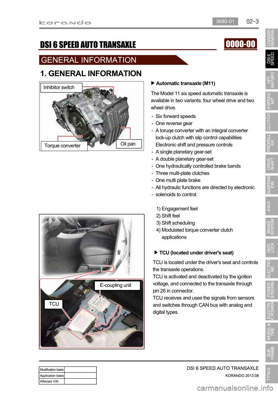
Automatic transaxle (M11)
The Model 11 six speed automatic transaxle is
available in two variants: four wheel drive and two
wheel drive.
Six forward speeds
One reverse gear
A toruqe converter with an integral converter
lock-up clutch with slip control capabilities
Electronic shift and pressure controls
A single planetary gear-set
A double planetary gear-set
One hydraulically controlled brake bands
Three multi-plate clutches
One multi plate brake
All hydraulic functions are directed by electronic
solenoids to control: -
-
-
-
-
-
-
-
-
-
Engagement feel
Shift feel
Shift scheduling
Modulated torque converter clutch
applications 1)
2)
3)
4) Inhibitor switch
Oil pan
Torque converter
TCU (located under driver's seat)
TCU is located under the driver's seat and controls
the transaxle operations.
TCU is activated and deactivated by the ignition
voltage, and connected to the transaxle through
pin 26 in connector.
TCU receives and uses the signals from sensors
and switches through CAN bus with analog and
digital types.
E-coupling unit
TCU
Page 1005 of 1336
3680-01
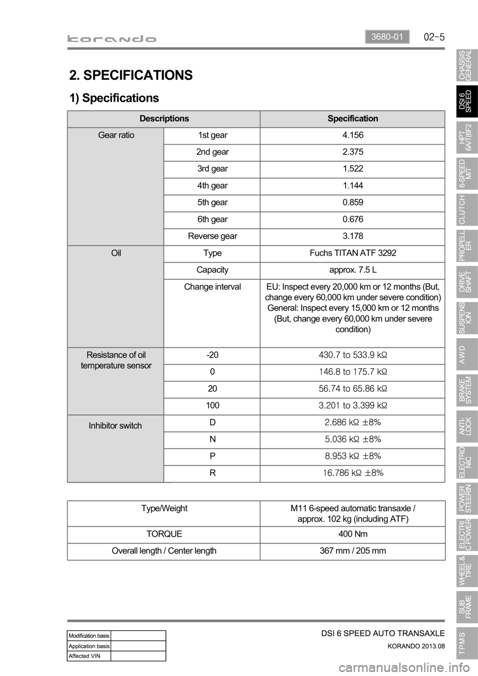
2. SPECIFICATIONS
1) Specifications
Type/Weight M11 6-speed automatic transaxle /
approx. 102 kg (including ATF)
TORQUE 400 Nm
Overall length / Center length 367 mm / 205 mm
Descriptions Specification
Gear ratio 1st gear 4.156
2nd gear 2.375
3rd gear 1.522
4th gear 1.144
5th gear 0.859
6th gear 0.676
Reverse gear 3.178
Oil Type Fuchs TITAN ATF 3292
Capacity approx. 7.5 L
Change interval EU: Inspect every 20,000 km or 12 months (But,
change every 60,000 km under severe condition)
General: Inspect every 15,000 km or 12 months
(But, change every 60,000 km under severe
condition)
Resistance of oil
temperature sensor-20
0
20
100
D
N
P
R
Inhibitor switch
Page 1007 of 1336
3680-01
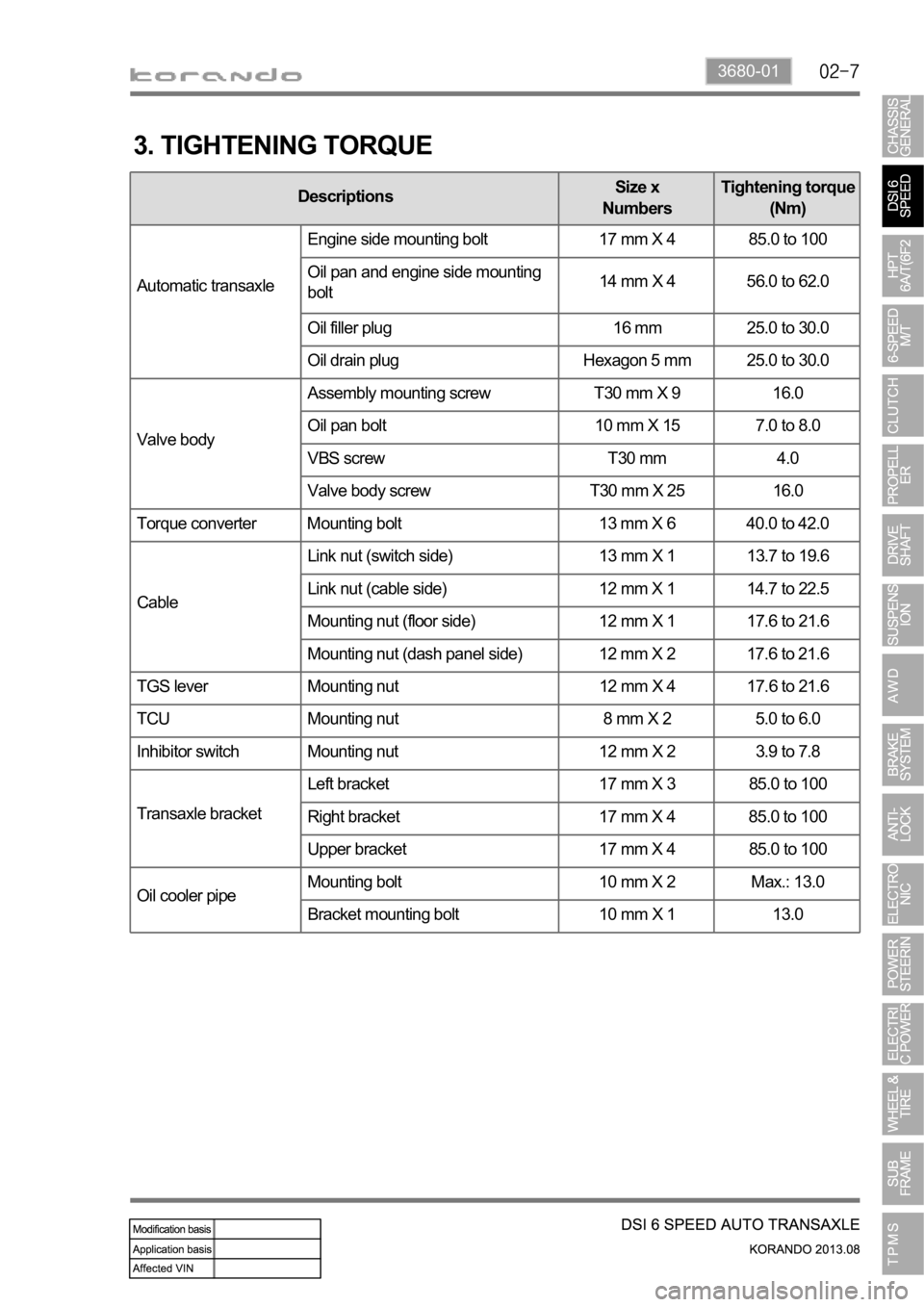
3. TIGHTENING TORQUE
DescriptionsSize x
NumbersTightening torque
(Nm)
Automatic transaxleEngine side mounting bolt 17 mm X 4 85.0 to 100
Oil pan and engine side mounting
bolt14 mm X 4 56.0 to 62.0
Oil filler plug 16 mm 25.0 to 30.0
Oil drain plug Hexagon 5 mm 25.0 to 30.0
Valve bodyAssembly mounting screw T30 mm X 9 16.0
Oil pan bolt 10 mm X 15 7.0 to 8.0
VBS screw T30 mm 4.0
Valve body screw T30 mm X 25 16.0
Torque converter Mounting bolt 13 mm X 6 40.0 to 42.0
CableLink nut (switch side) 13 mm X 1 13.7 to 19.6
Link nut (cable side) 12 mm X 1 14.7 to 22.5
Mounting nut (floor side) 12 mm X 1 17.6 to 21.6
Mounting nut (dash panel side) 12 mm X 2 17.6 to 21.6
TGS lever Mounting nut 12 mm X 4 17.6 to 21.6
TCU Mounting nut 8 mm X 2 5.0 to 6.0
Inhibitor switch Mounting nut 12 mm X 2 3.9 to 7.8
Transaxle bracketLeft bracket 17 mm X 3 85.0 to 100
Right bracket 17 mm X 4 85.0 to 100
Upper bracket 17 mm X 4 85.0 to 100
Oil cooler pipeMounting bolt 10 mm X 2 Max.: 13.0
Bracket mounting bolt 10 mm X 1 13.0
Page 1009 of 1336
3680-01
2. FEATURES
1) Advantages
Early Downshift with Hard Braking and Skip Shifts
When heavy braking is detected, the transaxle downshifts early and skips gears to provide increased
engine braking to provide gear selection for tip-in.
Gear Hold going Uphill/Downhill
If the accelerator pedal is released when traveling uphill, upshifts are prevented to reduce busyness on
grades. If the accelerator pedal is released when traveling downhill, upshifts are prevented to enhance
engine braking.
Drive and Reverse Engagement
A soft engagement feature avoids harsh take up of drive when selecting Drive or Reverse. This is
achieved by limiting engine speed and engine torque which results in a rapid, but progressive
engagement of either Drive or Reverse when moving from the Park or Neutral positions. Drive and
Reverse engagements from either Park or Neutral are performed in less than 2.2 seconds. There is no
drive engagement prevention strategy implemented on the transaxle system as there is sufficient engine
strategy to protect the system. However, reverse engagement is prevented until engine speed is less
than 1,400 rpm and the accelerator pedal position is less than 12% and vehicle speed is less than 10
km/h.
Converter Clutch Lock-Up In All Gears
The transaxle features converter clutch lock-up in all gears. This feature provides improved fuel economy
and vehicle performance. It also improves transaxle cooling efficiency when towing heavy loads at low
speeds, e.g. in city driving or hill terrain.
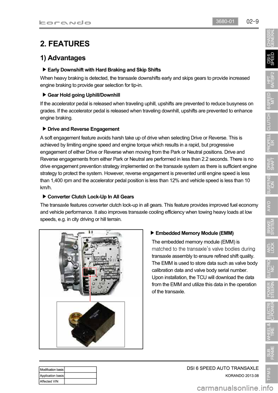
Embedded Memory Module (EMM)
The embedded memory module (EMM) is
transaxle assembly to ensure refined shift quality.
The EMM is used to store data such as valve body
calibration data and valve body serial number.
Upon installation, the TCU will download the data
from the EMM and utilize this data in the operation
of the transaxle.
Page 1011 of 1336
3680-01
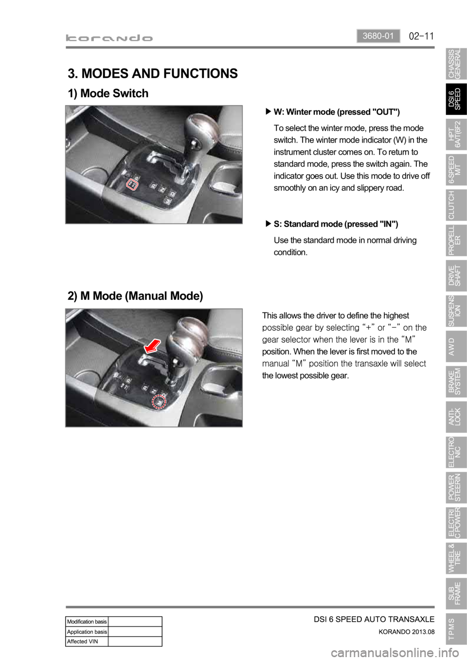
To select the winter mode, press the mode
switch. The winter mode indicator (W) in the
instrument cluster comes on. To return to
standard mode, press the switch again. The
indicator goes out. Use this mode to drive off
smoothly on an icy and slippery road.
3. MODES AND FUNCTIONS
1) Mode Switch
2) M Mode (Manual Mode)
This allows the driver to define the highest
position. When the lever is first moved to the
the lowest possible gear.W: Winter mode (pressed "OUT")
Use the standard mode in normal driving
condition. S: Standard mode (pressed "IN")
Page 1013 of 1336
3680-01
4. LIMP HOME MODE
When the transaxle is defective
In the event of a system fault, the TCU also provides for failure mode effect control (FMEC) to maintain
maximum functional operation of the transaxle.
In the event of a total loss of control or electrical power, the basic transaxle functions (Park, Reverse,
Neutral and Drive) are retained. The 4th and reverse gear ratios with the torque converter clutch in the
unlocked state are the retained gear states the hydraulic system supports without any electrical
assistance.
The TCU communicates with other vehicle electronic control modules by the controller area network
(CAN). If a major fault develops, the transaxle may automatically operate in a "limp home" (failure)
mode to enable the vehicle to be driven to an authorized dealer for repair.
The TCU also provides for transaxle diagnostics, which meet the requirements of OBD II legislation,
monitoring all components which may effect vehicle emissions. 1.
2.
3.
4.
When the transaxle overheats
Limp home mode may also be engaged if the battery charge falls below 8V.
If the transaxle overheats, the shift patterns will automatically change to enable improved transaxle
cooling.
During transaxle overheat, the instrument cluster transaxle selector position display and the over
cluster until normal transaxle operating temperature is reached. 1.
2.
3.
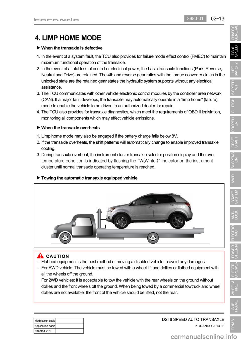
Towing the automatic transaxle equipped vehicle
Flat-bed equipment is the best method of moving a disabled vehicle to avoid any damages.
For AWD vehicle: The vehicle must be towed with a wheel lift and dollies or flatbed equipment with
all the wheels off the ground.
For 2WD vehicles: It is acceptable to tow the vehicle with the rear wheels on the ground without
dollies and the front wheels off the ground. When being towed by a commercial towtruck and wheel
dollies are not available, the front of the vehicle should be lifted, not the rear. -
-
Page 1015 of 1336
3680-01
This information is used by the TCU to decide which shift pattern to select and for shift energy
management. Electro-hydraulic solenoid valves and variable bleed solenoids control the transaxle gear
changes.
Six variable bleed solenoids and four on/off solenoids are used to direct transaxle fluid flow to control the
fluid pressure within the three clutches and two bands. Separate pressure regulators are used
exclusively for torque converter clutch control and main transaxle line pressure.
The TCU monitors all TCU inputs and outputs to confirm correct system operation. If a fault occurs the
TCU is able to perform default action and inform the driver of the problem through the instrument cluster
warning lights. Detailed information is available via trouble codes which can be read with the service tool.
Page 1017 of 1336
3680-01
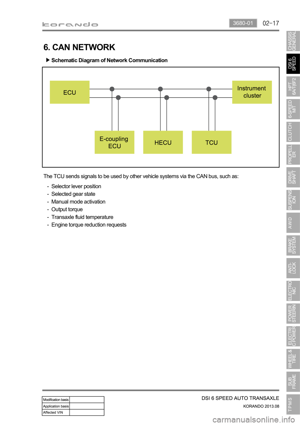
6. CAN NETWORK
The TCU sends signals to be used by other vehicle systems via the CAN bus, such as:
Selector lever position
Selected gear state
Manual mode activation
Output torque
Transaxle fluid temperature
Engine torque reduction requests -
-
-
-
-
-
Schematic Diagram of Network Communication