Page 1153 of 1336

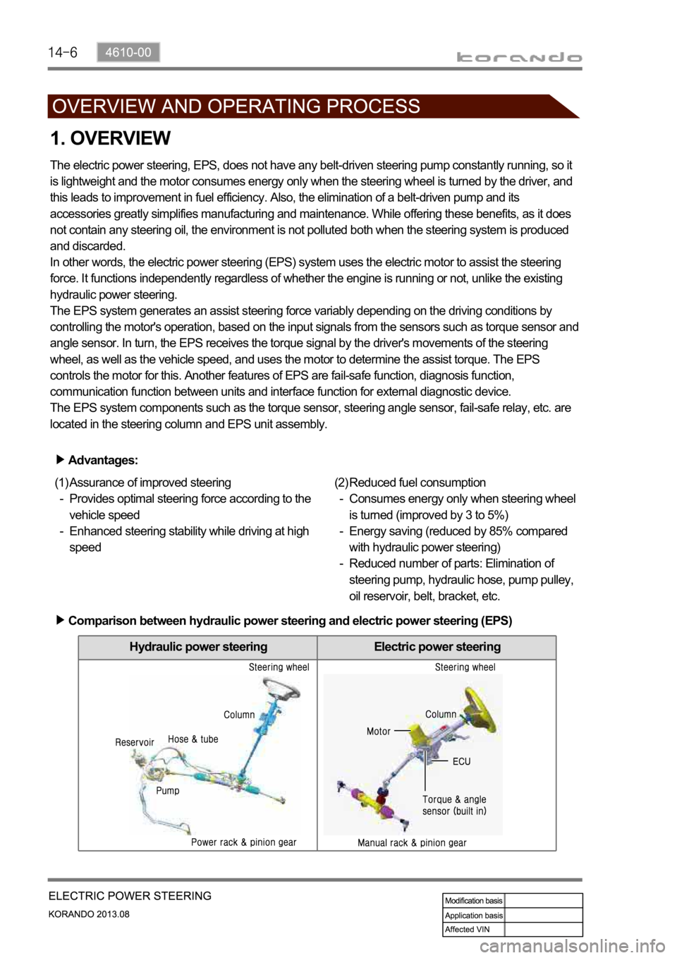
Hydraulic power steering Electric power steering
1. OVERVIEW
The electric power steering, EPS, does not have any belt-driven steering pump constantly running, so it
is lightweight and the motor consumes energy only when the steering wheel is turned by the driver, and
this leads to improvement in fuel efficiency. Also, the elimination of a belt-driven pump and its
accessories greatly simplifies manufacturing and maintenance. While offering these benefits, as it does
not contain any steering oil, the environment is not polluted both when the steering system is produced
and discarded.
In other words, the electric power steering (EPS) system uses the electric motor to assist the steering
force. It functions independently regardless of whether the engine is running or not, unlike the existing
hydraulic power steering.
The EPS system generates an assist steering force variably depending on the driving conditions by
controlling the motor's operation, based on the input signals from the sensors such as torque sensor and
angle sensor. In turn, the EPS receives the torque signal by the driver's movements of the steering
wheel, as well as the vehicle speed, and uses the motor to determine the assist torque. The EPS
controls the motor for this. Another features of EPS are fail-safe function, diagnosis function,
communication function between units and interface function for external diagnostic device.
The EPS system components such as the torque sensor, steering angle sensor, fail-safe relay, etc. are
located in the steering column and EPS unit assembly.
Advantages:
Assurance of improved steering
Provides optimal steering force according to the
vehicle speed
Enhanced steering stability while driving at high
speed (1)
-
-Reduced fuel consumption
Consumes energy only when steering wheel
is turned (improved by 3 to 5%)
Energy saving (reduced by 85% compared
with hydraulic power steering)
Reduced number of parts: Elimination of
steering pump, hydraulic hose, pump pulley,
oil reservoir, belt, bracket, etc. (2)
-
-
-
Comparison between hydraulic power steering and electric power steering (EPS)
Page 1158 of 1336

1. OVERVIEW
A radial tire uses a cord angle of 90 degrees. That is, the cord material runs in a radial or direct line from
one bead to the other across the tread. In addition, a radial tire has a belt overwrap under the tread
surface to provide greater structural stability. The belt overwrap of a radial tire distortion while the radial
structure enables high speed driving.
Tire supports the weight of the vehicle, reduces the impact from the road and at the same time,
transmits the power to propel, brake and steer on the road. It also functions to maintain a
vessel of air.
There is wear limit mark on the tire, which protrudes as a strip shape located approximately 1.6 mm from
mark on the shoulder to let the driver find the wear mark easily. To measure the tire groove depth,
measure at any point other than the point which has a wear limit mark.
The tire is worn unevenly according to the driver's driving habit, improper servicing, low tire inflation
pressure, changed tire location, etc.
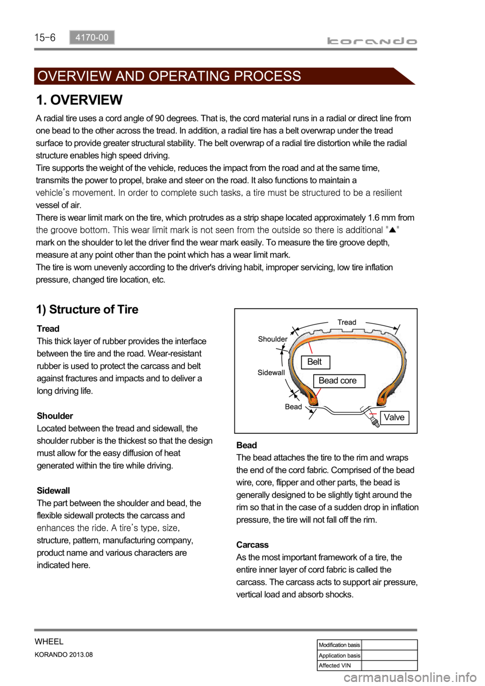
1) Structure of Tire
Tread
This thick layer of rubber provides the interface
between the tire and the road. Wear-resistant
rubber is used to protect the carcass and belt
against fractures and impacts and to deliver a
long driving life.
Shoulder
Located between the tread and sidewall, the
shoulder rubber is the thickest so that the design
must allow for the easy diffusion of heat
generated within the tire while driving.
Sidewall
The part between the shoulder and bead, the
flexible sidewall protects the carcass and
structure, pattern, manufacturing company,
product name and various characters are
indicated here. Bead
The bead attaches the tire to the rim and wraps
the end of the cord fabric. Comprised of the bead
wire, core, flipper and other parts, the bead is
generally designed to be slightly tight around the
rim so that in the case of a sudden drop in inflation
pressure, the tire will not fall off the rim.
Carcass
As the most important framework of a tire, the
entire inner layer of cord fabric is called the
carcass. The carcass acts to support air pressure,
vertical load and absorb shocks.
Valve
Belt
Bead core
Page 1202 of 1336

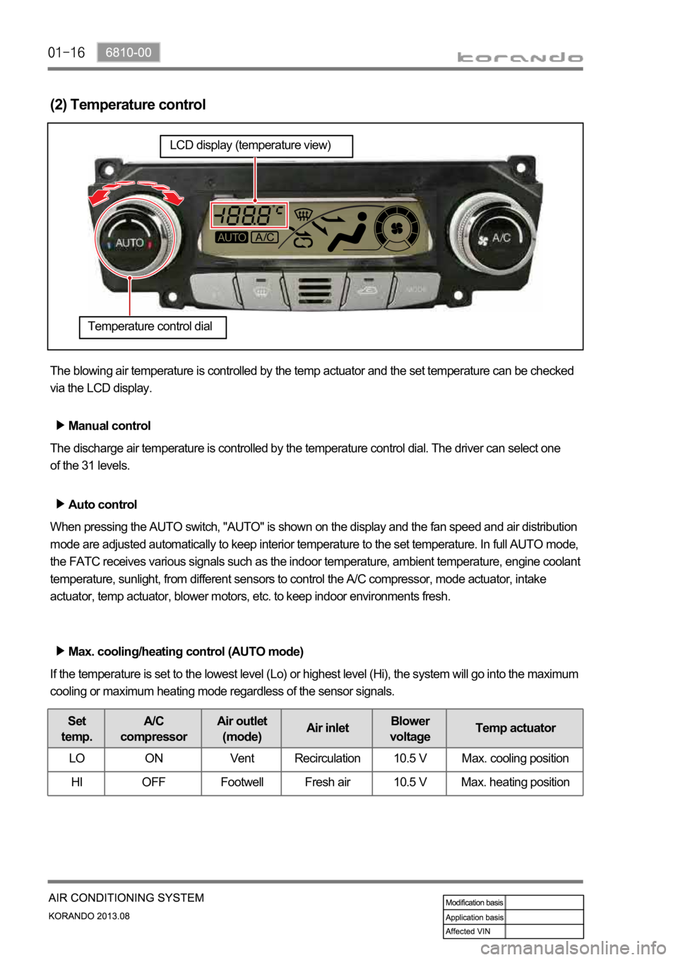
(2) Temperature control
The blowing air temperature is controlled by the temp actuator and the set temperature can be checked
via the LCD display.
Manual control
The discharge air temperature is controlled by the temperature control dial. The driver can select one
of the 31 levels.
Auto control
When pressing the AUTO switch, "AUTO" is shown on the display and the fan speed and air distribution
mode are adjusted automatically to keep interior temperature to the set temperature. In full AUTO mode,
the FATC receives various signals such as the indoor temperature, ambient temperature, engine coolant
temperature, sunlight, from different sensors to control the A/C compressor, mode actuator, intake
actuator, temp actuator, blower motors, etc. to keep indoor environments fresh.
Max. cooling/heating control (AUTO mode)
If the temperature is set to the lowest level (Lo) or highest level (Hi), the system will go into the maximum
cooling or maximum heating mode regardless of the sensor signals.
Set
temp.A/C
compressorAir outlet
(mode)Air inletBlower
voltageTemp actuator
LO ON Vent Recirculation 10.5 V Max. cooling position
HI OFF Footwell Fresh air 10.5 V Max. heating position
Temperature control dial
LCD display (temperature view)
Page 1203 of 1336

6810-00
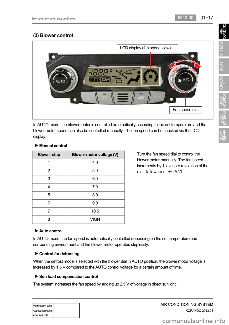
(3) Blower control
In AUTO mode, the blower motor is controlled automatically according to the set temperature and the
blower motor speed can also be controlled manually. The fan speed can be checked via the LCD
display.
Manual control
Auto control
In AUTO mode, the fan speed is automatically controlled depending on the set temperature and
surrounding environment and the blower motor operates steplessly.
Sun load compensation control
The system increases the fan speed by adding up 2.5 V of voltage in direct sunlight.
Blower step Blower motor voltage (V)
1 4.0
25.0
36.0
47.0
5 8.0
6 9.0
7 10.5
8 VIGN
Control for defrosting
When the defrost mode is selected with the blower dial in AUTO position, the blower motor voltage is
increased by 1.5 V compared to the AUTO control voltage for a certain amount of time. Turn the fan speed dial to control the
blower motor manually. The fan speed
increments by 1 level per revolution of the
Fan speed dial
LCD display (fan speed view)
Page 1295 of 1336
7340-00
2. OPERATING PROCESS
1) Sunroof Switch
This can be closed or open manually to block sunlight when the sunroof function is not in use. The sunroof glass can be open in two steps and can be tilted by the switch operation. The sunroof switches are included in the overhead console switches and consists of the TILT,
CLOSE and OPEN switches.
TILT
CLOSE
OPEN
Sun shade panel Sunroof glass Sunroof switch
Opens only rear section of the sunroof.
Closes the sunroof.
Opens the sunroof.
Sunroof glass
Sun shade panel