Page 194 of 1336
0000-00
4. CODING
1) Engine Variant Coding
Description Selection Coding
Additional heater
NOPTC auxiliary heater is the standard equipment in
this vehicle.
Select "YES". YES
Gear box 5-speed M/T M/T : 6-speed M/T
A/T : 6-speed A/T (DSI 6AT)
6-speed M/T
5-speed A/T (DC 5 AT)
7-speed A/T (DC 7 AT)
6-speed A/T (DC 6 AT)
Immobilizer
NOImmobilizer is the standard equipment in this
behicle.
Select "YES". YES
FAN 2 relays Select "2 relays".
FAN
Not defind
Engine level control
NOEngine level control system is not available in this
vehicle.
Select "NO". YES
SKM key NO with Smart key : Select "YES".
YES
Glow plug
Relay (K-Line)AQGS is the standard equipment in this vehicle.
Select "AQGS".
AQGS (CAN)
A/C NO Select the appropriate system.
YES
Not defind
Vehicle speed
sensorCAN with ABS or ESP : Select "CAN".
WIRE
Cruise control NO with cruise control system : Select "YES".
YES
G-sensor NO with 2WD ABS and non-ABS : Select "NO"
with 4WD ABS and ESP : Select "YES"
YES
Page 988 of 1336
Front sub frame with HPS type steering gear box assembly
The front sub frame consists of 4 body bush mountings and 2 transmission
bush mountings which reduce the vibration from the powertrain and road,
and also control the torque. And the frame is equipped with hydraulic
pressure pipe of the HPS type steering gear box.
4. SUB FRAME AND STEERING GEAR BOX LAYOUT
Front sub frame with EPS type steering gear box assembly
This kind of front sub frame system has the same mounting structure with
the frame with HPS. But the EPS type steering gear box has no hydraulic
pressure pipe since it is driven by the electric motor.
Rear side
Front sideHPS type steering
gear box assembly
Front sub frame
assembly
Rear side
Front side
EPS type steering
gear box assembly
Front sub frame
assembly
Page 996 of 1336

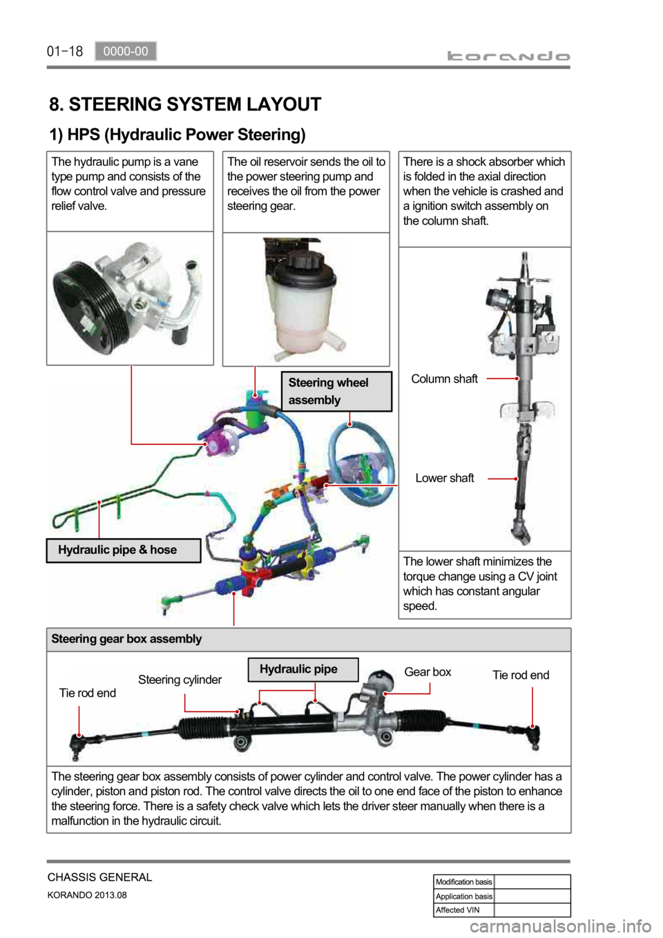
Steering gear box assembly
The steering gear box assembly consists of power cylinder and control valve. The power cylinder has a
cylinder, piston and piston rod. The control valve directs the oil to one end face of the piston to enhance
the steering force. There is a safety check valve which lets the driver steer manually when there is a
malfunction in the hydraulic circuit.
8. STEERING SYSTEM LAYOUT
1) HPS (Hydraulic Power Steering)
The hydraulic pump is a vane
type pump and consists of the
flow control valve and pressure
relief valve.The oil reservoir sends the oil to
the power steering pump and
receives the oil from the power
steering gear.There is a shock absorber which
is folded in the axial direction
when the vehicle is crashed and
a ignition switch assembly on
the column shaft.
The lower shaft minimizes the
torque change using a CV joint
which has constant angular
speed.
Tie rod endSteering cylinderGear box
Tie rod end
Hydraulic pipeColumn shaft
Lower shaft
Steering wheel
assembly
Hydraulic pipe & hose
Page 997 of 1336

0000-00
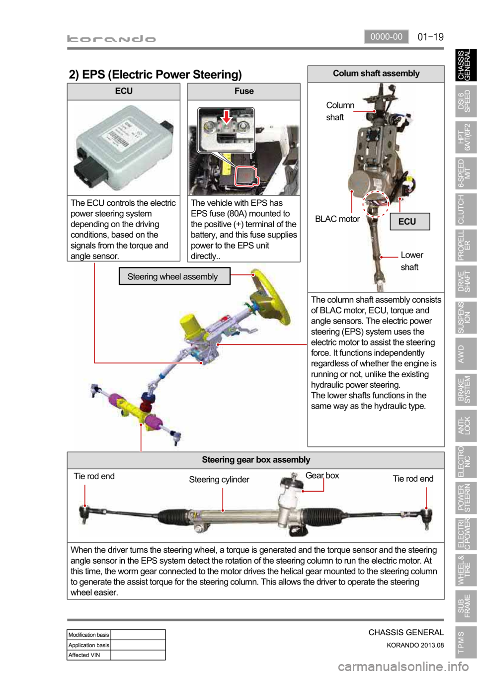
ECU
The ECU controls the electric
power steering system
depending on the driving
conditions, based on the
signals from the torque and
angle sensor.
2) EPS (Electric Power Steering)
Fuse
The vehicle with EPS has
EPS fuse (80A) mounted to
the positive (+) terminal of the
battery, and this fuse supplies
power to the EPS unit
directly..
Steering gear box assembly
When the driver turns the steering wheel, a torque is generated and the torque sensor and the steering
angle sensor in the EPS system detect the rotation of the steering column to run the electric motor. At
this time, the worm gear connected to the motor drives the helical gear mounted to the steering column
to generate the assist torque for the steering column. This allows the driver to operate the steering
wheel easier.
ECU
Tie rod end
Tie rod end Gear boxSteering cylinder
Steering wheel assembly
BLAC motor
Lower
shaft Column
shaft
Colum shaft assembly
The column shaft assembly consists
of BLAC motor, ECU, torque and
angle sensors. The electric power
steering (EPS) system uses the
electric motor to assist the steering
force. It functions independently
regardless of whether the engine is
running or not, unlike the existing
hydraulic power steering.
The lower shafts functions in the
same way as the hydraulic type.
Page 1145 of 1336
0000-00
1. SPECIFICATION (HPS)
Component Item Specification
Steering wheel Type 3-spoke
Outside diameter
Number of revolutions 3.09 rotations
Heated wire Simple ON/OFF
Gear box Type Rack and pinion
Gear ratio 46.94
Rack stroke
Steering angle Inner
Outer
Wheel alignment Toe-in
Oil pump Type Vane (removable pump and reservoir)
Maximum pressure
Displacement
Pulley diameter
Steering column Tilting angle Up + 2.0 deg
Down - 3.0 deg
Lower shaft Type Ball slip
Steering oil Oil type S-PSF 3
Oil reservoir capacity
Change interval EU (Diesel): Check and add at every 20,000
km
GEN (Diesel, Gasoline): Check and add at
every 15,000 km
Turning capability Min. turning radius 5.35 m
Page 1146 of 1336
2. TIGHTENING TORQUE
Item Tightening torque Remark
1. Power steering reservoir mounting bolt 8.8 to 13.7 Nm 12 mm x 2 EA
2. Power steering
pumpUpper mounting bolt/nut
13 mm x 1 EA
Lower mounting bolt
12 mm x 2 EA
3. Oil pipe Eye bolt (pump side) 53.9 to 63.7 Nm 22 mm
Steering gear box side nut 31.4 to 37.2 Nm 17 mm
4. Oil pipe bracket mounting nut 6.8 to 10.8 Nm 10 mm
5. Tie rod end lock nut 44.1 to 53.9 Nm 17 mm
6. Tie rod nut 63.7 to 78.4 Nm 22 mm
7. Lower shaft Lower mounting bolt
(gear box side)17.6 to 24.5 Nm 12 mm
Upper mounting bolt (column
side)17.6 to 24.5 Nm 12 mm
8. Column shaft Lower mounting bolt 19.6 to 24.5 Nm 12 mm
Upper mounting nut 19.6 to 24.5 Nm 12 mm
9. Steering wheel nut 39.2 to 49.1 Nm 22 mm
10. Loosened gear box mounting bolt/nut Left: 98.0 to 127.4 Nm 17 mm
Right: 88.3 to 107.9 Nm 17 mm
11. Heat shield mounting bolt 8.8 to 13.7 Nm 12 mm x 2 EA
Page 1148 of 1336

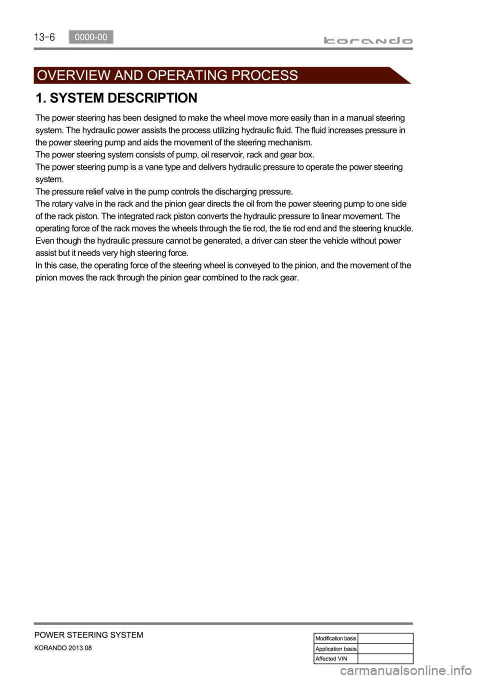
1. SYSTEM DESCRIPTION
The power steering has been designed to make the wheel move more easily than in a manual steering
system. The hydraulic power assists the process utilizing hydraulic fluid. The fluid increases pressure in
the power steering pump and aids the movement of the steering mechanism.
The power steering system consists of pump, oil reservoir, rack and gear box.
The power steering pump is a vane type and delivers hydraulic pressure to operate the power steering
system.
The pressure relief valve in the pump controls the discharging pressure.
The rotary valve in the rack and the pinion gear directs the oil from the power steering pump to one side
of the rack piston. The integrated rack piston converts the hydraulic pressure to linear movement. The
operating force of the rack moves the wheels through the tie rod, the tie rod end and the steering knuckle.
Even though the hydraulic pressure cannot be generated, a driver can steer the vehicle without power
assist but it needs very high steering force.
In this case, the operating force of the steering wheel is conveyed to the pinion, and the movement of the
pinion moves the rack through the pinion gear combined to the rack gear.
Page 1149 of 1336
0000-00
Installation of steering
gear box and pipe
Installation of reservoir and hoseInstallation of power steering pump
and pipe
2. SYSTEM LAYOUT
The steering pump is driven by the engine power through a belt. This pump circulates the power steering
oil from the reservoir -> steering pump -> oil supply pipe -> steering gear box -> oil return pipe ->
reservoir to perform steering operations.
Return pipe
Supply pipe