Page 876 of 1336
8510-00
3) Cruise Control Switch
Cruise control switch
The cruise control is an automatic speed control system that maintains a desired driving speed without
using the accelerator pedal. The cruise control switch is fitted to the bottom right section of the steering
wheel. When this switch is operated, the AUTO CRUISE or ECO lamp on the instrument cluster comes
on.
The cruise control switch has a fivefold switch in it. The engine ECU can determine the current driving
condition since the resistance varies depending on the operation of the switch.
The cruise control system is operated at vehicle speed of between 38 km/h and 150 km/h. The manual
transmission is operated in the range of 3rd gear or higher.
This function can be used at the following traffic condition. (It is important to be careful for using this
function)
Cruise control (ON)
Cruise control (OFF)
Cruise control (Acceleration)Cruise control (Deceleration)
Cruise control (Reset)
Page 877 of 1336
Horn (high) Horn (low)
Theft deterrent horn
Theft deterrent horn
4) Horn Switch
Two horns are installed in the radiator grille at the bottom of both sides (one on each side). There is
another horn installed at the bottom of the battery tray side in the engine compartment for theft alarm.
Operating the horn switch on the steering wheel applies the power to the horn relay to operate both
horns (Dual horn). The theft deterrent horn is controlled by the BCM in armed mode regardless of the
horn relay operation.
Horn (dual horn)
Horn switch
Page 984 of 1336

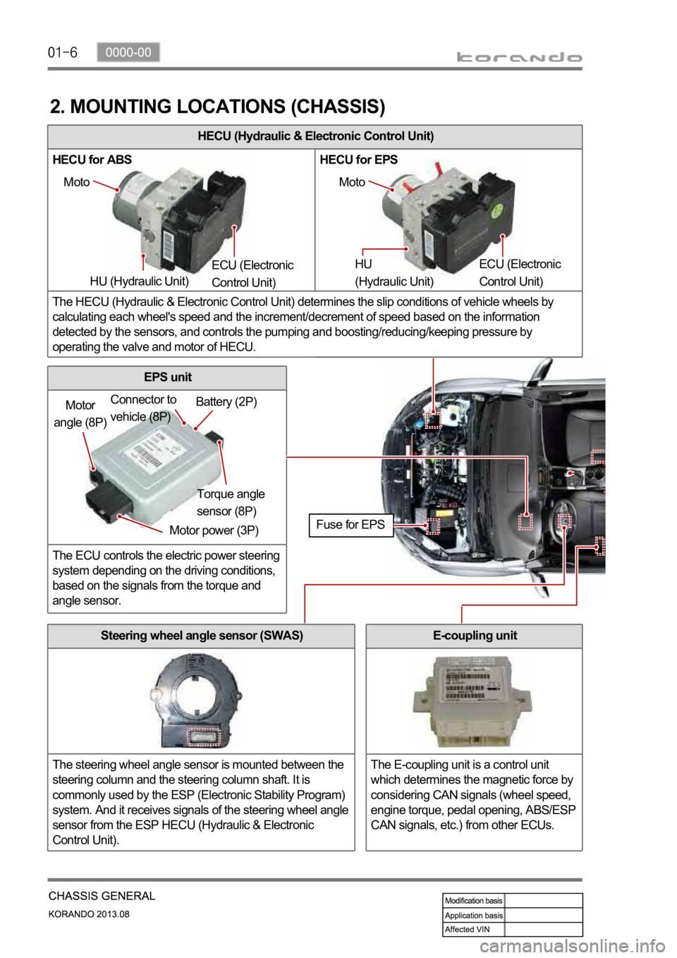
HECU (Hydraulic & Electronic Control Unit)
HECU for ABS HECU for EPS
The HECU (Hydraulic & Electronic Control Unit) determines the slip conditions of vehicle wheels by
calculating each wheel's speed and the increment/decrement of speed based on the information
detected by the sensors, and controls the pumping and boosting/reducing/keeping pressure by
operating the valve and motor of HECU.
2. MOUNTING LOCATIONS (CHASSIS)
Moto
HU (Hydraulic Unit) ECU (Electronic
Control Unit) Moto
HU
(Hydraulic Unit) ECU (Electronic
Control Unit)
Motor
angle (8P)
Motor power (3P)Torque angle
sensor (8P) Battery (2P) Connector to
vehicle (8P)
Fuse for EPS
Steering wheel angle sensor (SWAS)
The steering wheel angle sensor is mounted between the
steering column and the steering column shaft. It is
commonly used by the ESP (Electronic Stability Program)
system. And it receives signals of the steering wheel angle
sensor from the ESP HECU (Hydraulic & Electronic
Control Unit).
EPS unit
The ECU controls the electric power steering
system depending on the driving conditions,
based on the signals from the torque and
angle sensor.
E-coupling unit
The E-coupling unit is a control unit
which determines the magnetic force by
considering CAN signals (wheel speed,
engine torque, pedal opening, ABS/ESP
CAN signals, etc.) from other ECUs.
Page 985 of 1336

0000-00
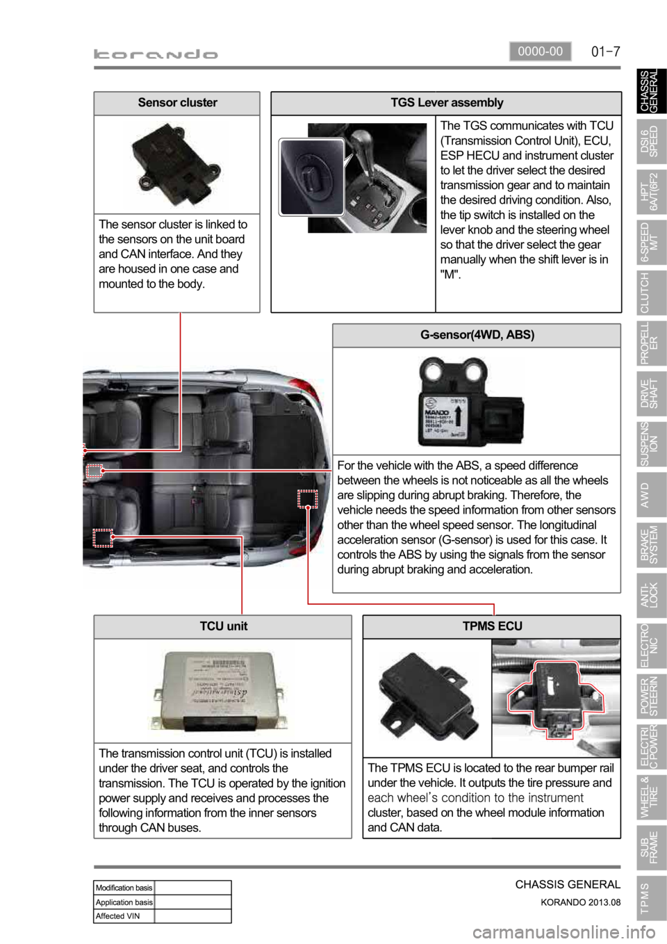
TPMS ECU
The TPMS ECU is located to the rear bumper rail
under the vehicle. It outputs the tire pressure and
cluster, based on the wheel module information
and CAN data.
G-sensor(4WD, ABS)
For the vehicle with the ABS, a speed difference
between the wheels is not noticeable as all the wheels
are slipping during abrupt braking. Therefore, the
vehicle needs the speed information from other sensors
other than the wheel speed sensor. The longitudinal
acceleration sensor (G-sensor) is used for this case. It
controls the ABS by using the signals from the sensor
during abrupt braking and acceleration.
TCU unit
The transmission control unit (TCU) is installed
under the driver seat, and controls the
transmission. The TCU is operated by the ignition
power supply and receives and processes the
following information from the inner sensors
through CAN buses.
TGS Lever assembly
The TGS communicates with TCU
(Transmission Control Unit), ECU,
ESP HECU and instrument cluster
to let the driver select the desired
transmission gear and to maintain
the desired driving condition. Also,
the tip switch is installed on the
lever knob and the steering wheel
so that the driver select the gear
manually when the shift lever is in
"M".Sensor cluster
The sensor cluster is linked to
the sensors on the unit board
and CAN interface. And they
are housed in one case and
mounted to the body.
Page 988 of 1336
Front sub frame with HPS type steering gear box assembly
The front sub frame consists of 4 body bush mountings and 2 transmission
bush mountings which reduce the vibration from the powertrain and road,
and also control the torque. And the frame is equipped with hydraulic
pressure pipe of the HPS type steering gear box.
4. SUB FRAME AND STEERING GEAR BOX LAYOUT
Front sub frame with EPS type steering gear box assembly
This kind of front sub frame system has the same mounting structure with
the frame with HPS. But the EPS type steering gear box has no hydraulic
pressure pipe since it is driven by the electric motor.
Rear side
Front sideHPS type steering
gear box assembly
Front sub frame
assembly
Rear side
Front side
EPS type steering
gear box assembly
Front sub frame
assembly
Page 990 of 1336
Stabilizer bar assembly
The stabilizer bar assembly is not activated if the left/right
wheels move up/down simultaneously, but if both wheels
move up/down differently it is activated with frame to
minimize the tilting of the body.
5. FRONT SUSPENSION COMPONENT LAYOUT
Front suspension supports the vehicle weight and absorber the vibration from tires. And, in this type of
suspension, the steering linkage tie rod is mounted on the knuckle. The Macpherson Strut suspension
is an independent suspension which has a spring on the strut with a built-in shock absorber. The lower
arm is installed on sub frame and large strut damper is installed on the knuckle to support the tire.
Lower arm assembly
The lower arm assembly connects the frame and
knuckle. It supports the load transferred to the tire
knuckle, relieves the impact from the vehicle and ground
conditions, and ensures driving stability.
Stabilizer bar
Bushing
Clamp
Link
Page 992 of 1336
6. REAR SUSPENSION COMPONENT LAYOUT
Multi-link type suspension is the independent suspension. It provides good ride comfort and drivability
by reducing the coil spring weight. Also, it increases the space for passenger compartment by lowering
the floor.
This type of suspension consists of multiple links such as trailing arm, upper arm, lower arm and track
rod.
Shock absorber assembly
This vehicle uses the gas
shock absorber. This
relieves the vertical
vibrations of vehicle to
provide ride comforts,
prevents the spring break,
enhances drivability, and
extends the life span of
steering components.
Upper arm assembly
Upper arm is installed between knuckle and sub
frame and controls the lateral load and vehicle
height.
Trailing arm assembly
Trailing arm is installed between knuckle and
vehicle body and controls the front and rear load.
Track rod assembly
Track rod is installed between knuckle and rear
sub frame and controls and compensates the
lateral load.
Page 996 of 1336

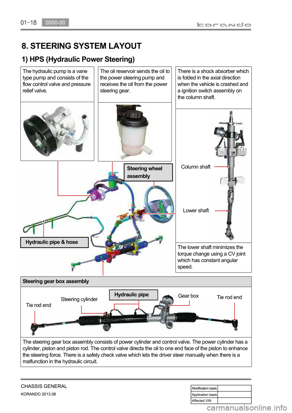
Steering gear box assembly
The steering gear box assembly consists of power cylinder and control valve. The power cylinder has a
cylinder, piston and piston rod. The control valve directs the oil to one end face of the piston to enhance
the steering force. There is a safety check valve which lets the driver steer manually when there is a
malfunction in the hydraulic circuit.
8. STEERING SYSTEM LAYOUT
1) HPS (Hydraulic Power Steering)
The hydraulic pump is a vane
type pump and consists of the
flow control valve and pressure
relief valve.The oil reservoir sends the oil to
the power steering pump and
receives the oil from the power
steering gear.There is a shock absorber which
is folded in the axial direction
when the vehicle is crashed and
a ignition switch assembly on
the column shaft.
The lower shaft minimizes the
torque change using a CV joint
which has constant angular
speed.
Tie rod endSteering cylinderGear box
Tie rod end
Hydraulic pipeColumn shaft
Lower shaft
Steering wheel
assembly
Hydraulic pipe & hose