Page 1032 of 1336
3. SPECIFICATIONS
1) Specifications
Type/Weight 6F24 6-speed automatic transaxle /
approx. 86 kg (including ATF)
TORQUE 230 Nm
Overall length / Center length 373.1 mm / 204 mm
Descriptions Specification
Gear ratio 1st gear 4.212
2nd gear 2.637
3rd gear 1.800
4th gear 1.386
5th gear 1.000
6th gear 0.772
Reverse gear 3.385
Shift pattern Variable
Shift range 4 Range (P-R-N-D) + Manual mode
Shift range valve VFS : 6EA
Planetary gear 3EA (Front, Middle, Rear)
Clutch 2EA
Brake 3EA
O.W.C 1EA
Oil Type ATF SP-IV M
Capacity approx. 7.1 L
Change interval Maintenance free. However, under the severe
conditions or commercially used, change the oil at
every 100,000 km (EU: 90,000 km).
Resistance of oil
temperature sensor-20
0
20
100
Weight 2WD 87.5kg
4WD 88.5kg
Page 1034 of 1336

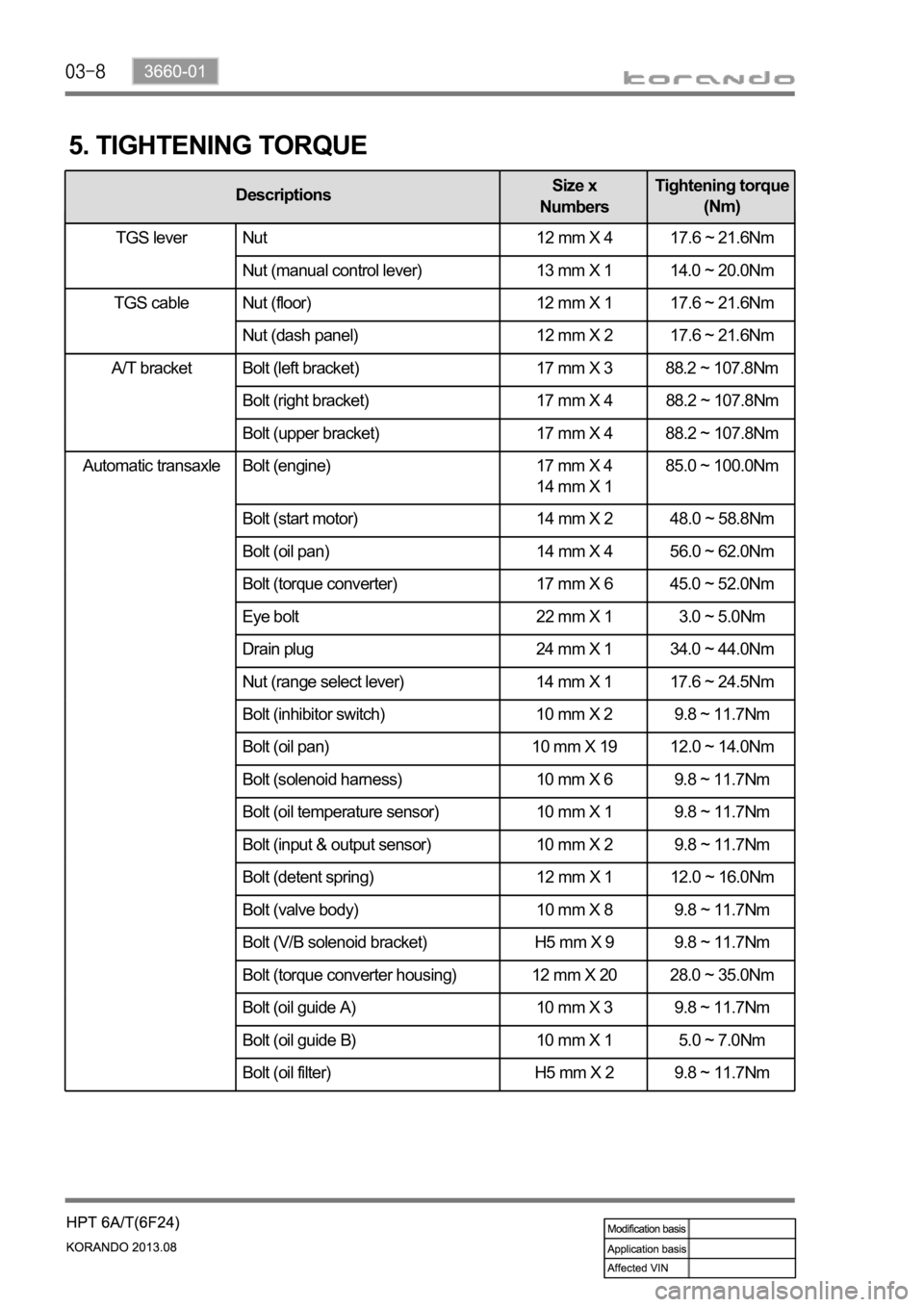
Automatic transaxle Bolt (engine) 17 mm X 4
14 mm X 1 85.0 ~ 100.0Nm
Bolt (start motor) 14 mm X 2 48.0 ~ 58.8Nm
Bolt (oil pan) 14 mm X 4 56.0 ~ 62.0Nm
Bolt (torque converter) 17 mm X 6 45.0 ~ 52.0Nm
Eye bolt 22 mm X 1 3.0 ~ 5.0Nm
Drain plug 24 mm X 1 34.0 ~ 44.0Nm
Nut (range select lever) 14 mm X 1 17.6 ~ 24.5Nm
Bolt (inhibitor switch) 10 mm X 2 9.8 ~ 11.7Nm
Bolt (oil pan) 10 mm X 19 12.0 ~ 14.0Nm
Bolt (solenoid harness) 10 mm X 6 9.8 ~ 11.7Nm
Bolt (oil temperature sensor) 10 mm X 1 9.8 ~ 11.7Nm
Bolt (input & output sensor) 10 mm X 2 9.8 ~ 11.7Nm
Bolt (detent spring) 12 mm X 1 12.0 ~ 16.0Nm
Bolt (valve body) 10 mm X 8 9.8 ~ 11.7Nm
Bolt (V/B solenoid bracket) H5 mm X 9 9.8 ~ 11.7Nm
Bolt (torque converter housing) 12 mm X 20 28.0 ~ 35.0Nm
Bolt (oil guide A) 10 mm X 3 9.8 ~ 11.7Nm
Bolt (oil guide B) 10 mm X 1 5.0 ~ 7.0Nm
Bolt (oil filter) H5 mm X 2 9.8 ~ 11.7Nm
5. TIGHTENING TORQUE
DescriptionsSize x
NumbersTightening torque
(Nm)
TGS lever Nut 12 mm X 4 17.6 ~ 21.6Nm
Nut (manual control lever) 13 mm X 1 14.0 ~ 20.0Nm
Nut (floor) 12 mm X 1 17.6 ~ 21.6Nm
Nut (dash panel) 12 mm X 2 17.6 ~ 21.6Nm
A/T bracket Bolt (left bracket) 17 mm X 3 88.2 ~ 107.8Nm
Bolt (right bracket) 17 mm X 4 88.2 ~ 107.8Nm
Bolt (upper bracket) 17 mm X 4 88.2 ~ 107.8Nm
TGS lever
TGS cable
Page 1037 of 1336

3660-01
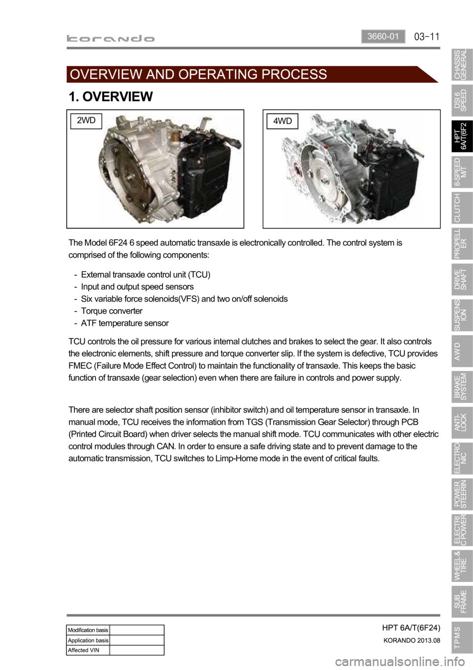
1. OVERVIEW
2WD4WD
The Model 6F24 6 speed automatic transaxle is electronically controlled. The control system is
comprised of the following components:
External transaxle control unit (TCU)
Input and output speed sensors
Six variable force solenoids(VFS) and two on/off solenoids
Torque converter
ATF temperature sensor -
-
-
-
-
TCU controls the oil pressure for various internal clutches and brakes to select the gear. It also controls
the electronic elements, shift pressure and torque converter slip. If the system is defective, TCU provides
FMEC (Failure Mode Effect Control) to maintain the functionality of transaxle. This keeps the basic
function of transaxle (gear selection) even when there are failure in controls and power supply.
There are selector shaft position sensor (inhibitor switch) and oil temperature sensor in transaxle. In
manual mode, TCU receives the information from TGS (Transmission Gear Selector) through PCB
(Printed Circuit Board) when driver selects the manual shift mode. TCU communicates with other electric
control modules through CAN. In order to ensure a safe driving state and to prevent damage to the
automatic transmission, TCU switches to Limp-Home mode in the event of critical faults.
Page 1043 of 1336

3660-01
5. TRANSAXLE ELECTRONIC CONTROL SYSTEM
1) General Information
The transmission control unit (TCU) and its input/output network control the following transmission
operations:
Shift timing
Line pressure
Clutch pressure (shift feel)
Torque converter clutch -
-
-
-
also uses these signals when determining transaxle operating strategy. Using all of these input signals,
the TCU can determine when the time and conditions are right for a shift, or when to apply or release the
torque converter clutch. It will also determine the pressure needed to optimise shift feel.
2) TCU (Transmission Control Unit)
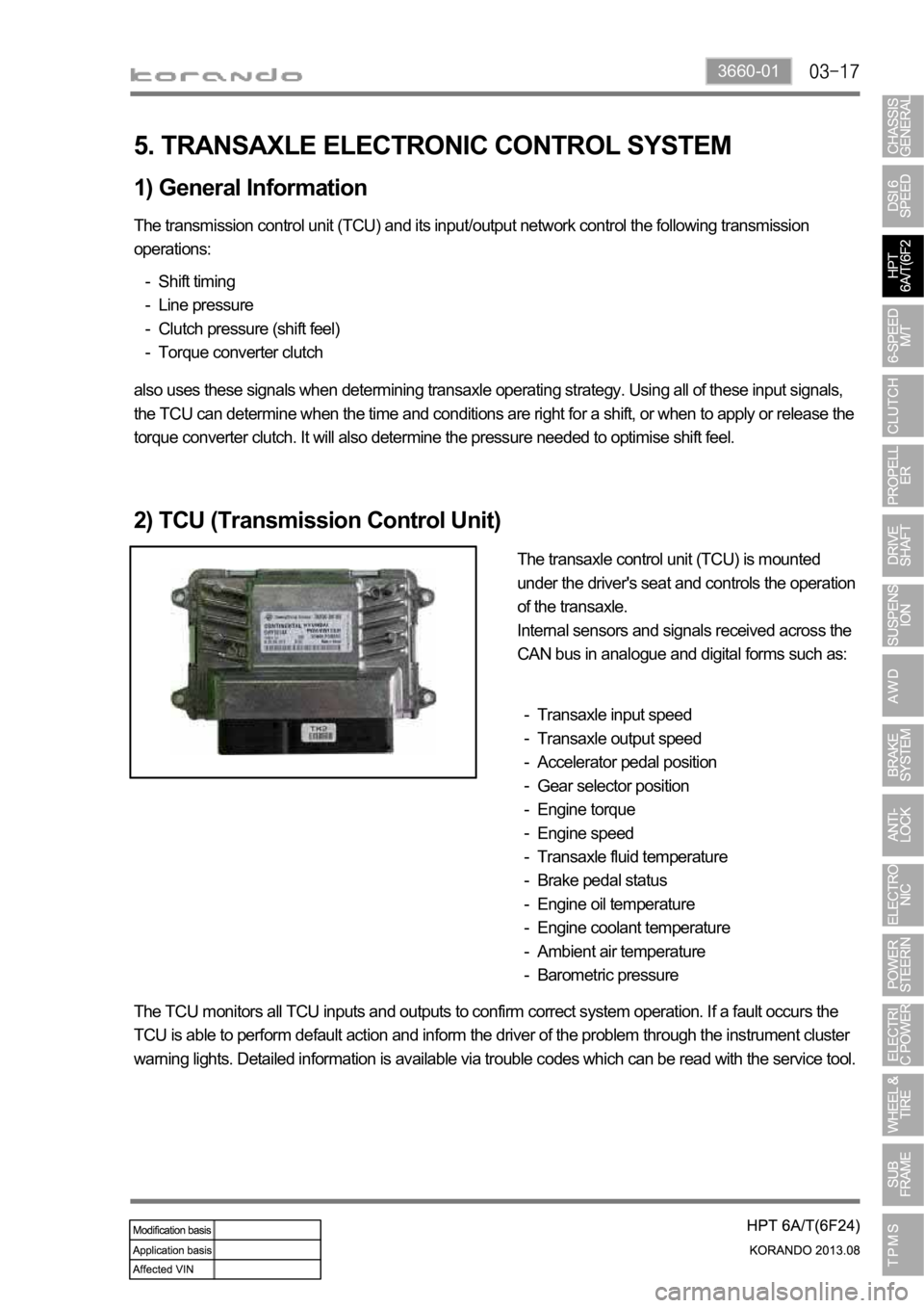
The transaxle control unit (TCU) is mounted
under the driver's seat and controls the operation
of the transaxle.
Internal sensors and signals received across the
CAN bus in analogue and digital forms such as:
Transaxle input speed
Transaxle output speed
Accelerator pedal position
Gear selector position
Engine torque
Engine speed
Transaxle fluid temperature
Brake pedal status
Engine oil temperature
Engine coolant temperature
Ambient air temperature
Barometric pressure -
-
-
-
-
-
-
-
-
-
-
-
The TCU monitors all TCU inputs and outputs to confirm correct system operation. If a fault occurs the
TCU is able to perform default action and inform the driver of the problem through the instrument cluster
warning lights. Detailed information is available via trouble codes which can be read with the service tool.
Page 1085 of 1336
0000-00
1. SPECIFICATION
Unit Description Specification
PTU
(Power Transfer Unit)Gear ratio 2.929
Numbers of helical gear 22/39
Numbers of hypoid gear 23/38
Oil IDEMITSU LW 80W/90
Oil capacity
Operating temperature
E-coupling Maximum torque 1,000 Nm
Operating temperature
Numbers of main clutch Outer: 11, Inner: 11
Numbers of pilot clutch Outer: 4, Inner: 3
Coil windings 240 turns
Weight 8 kg
Oil ECF107 (ATF based EMCD special oil)
Oil capacity 0.145 L (145 ml)
Page 1226 of 1336
8810-00
1. SPECIFICATIONS
Item Item Specification
Air bag unit (SDM)Voltage range 8.0 V to 16.0 V
Voltage for system diagnosis and
SDM self diagnosis8.0 V to 16.0 V
Voltage for communication
between front and side impact
sensors7.0 V to 16.0 V
Storage temperature
Operating temperature
Air bag module and seat belt
pretensioner0.4 A for 10 seconds
1.2 A for 2 ms
Front and side impact sensorsOperating temperature
Power voltage 5.0 to 11.0 V
Measurement range 5.0 to 11.0 V
Contact CoilRated voltage 12.0 V
Voltage range 9.0 V to 16.0 V
Air bag circuit resistance
Current capacity 5.0 A
Rotation 2.1 rotations for each (LH/RH)
direction
Replacement interval Change at every 10 years