2013 SSANGYONG KORANDO belt
[x] Cancel search: beltPage 829 of 1336

8010-01
Pin No.Message
Operating condition
Ambient temperature:
indicates air temperature
outside controlTRIP switch
Trip AReset: Press and hold the Trip switch
for more than 1 second
Trip BReset: Press and hold the Trip switch
for more than 1 second
Distance to empty:
indicates a distance can be
driven with the fuel remaining
controlFactory-setting mode
Average fuel consumption:
indicates average fuel
controlReset: Press and hold the Trip switch
for more than 1 second
Instant fuel consumption:
indicates fuel consumption for
a short periodsTRIP switch
Illumination brightness:
indicates tail lamp brightness
controlBrightness control: Press and hold the
Trip switch for more than 1 second
Start-up screenLCD display shows this message for 2
seconds after ignition ON.
Driver's seat belt
reminderLCD display shows this message for 4
message.
DOT LCD message display
Pin No. Message Operating condition
Page 1000 of 1336

4) Basic Inspection
(1) Horn operation
Listen for the horn sound when pressing the horn pad on the steering wheel. -
(2) Brake operation
Check if there is any abnormal noise, unusually long braking distance, or uneven braking force. If the
brake warning lamp does not go out even after starting the engien or are flashing during driving,
have the brake system checked immediately.
Check the brake pipes and hoses for connection, oil leak, crack or interference after changing the
position of tires. When replacing the tires, check the brake disc for surface condition and wear.
Check the parking brake cable and brake operation. Shorten the checking interval if the parking
brake is used frequently. -
-
-
(3) Exhaust system
Be aware to any changes in sound or smell from the exhaust system. These may be caused by leak or
overheat. Have the exhaust system checked and repaired immediately.
Inspect the exhaust system including catalytic converter. Inspect all the components and body frame
near the exhaust system. -
-
(4) Tires
Unusual vibration of the steering wheel and seats or pulling to one side on the straight and level roads
may indicates the uneven tire inflation pressure or poor wheel balance. -
(5) Steering and suspension system
Inspect the front and rear suspension and the steering system for damage, looseness or missing
parts, signs of wear or lack of lubrication. Inspect the power steering line and the hoses for
connection, leak, crack and chafing. Inspect the drive axle boot and seals for damage, tear or leak.
Replace or repair the system if necessary. -
(6) Engine oil
Check the oil level when the engine is still warm and add the specified engine oil if necessary. -
(7) Coolant
Check the coolant level in the coolant reservoir, coolant conditions (contamination, foreign material),
and hoses for damage and leak. Replace or add the Ssangyong genuine coolant, if needed. -
(8) Engine drive belt
Check all drive belts on the engine for wear, crack and looseness. Retighten or replace the belt, if
needed. -
Page 1149 of 1336

0000-00
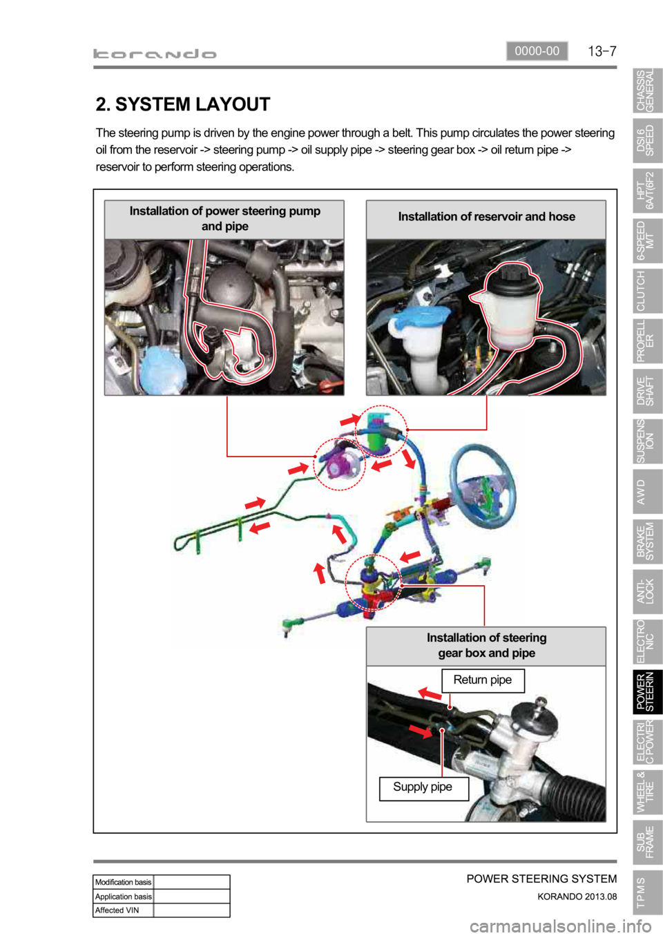
Installation of steering
gear box and pipe
Installation of reservoir and hoseInstallation of power steering pump
and pipe
2. SYSTEM LAYOUT
The steering pump is driven by the engine power through a belt. This pump circulates the power steering
oil from the reservoir -> steering pump -> oil supply pipe -> steering gear box -> oil return pipe ->
reservoir to perform steering operations.
Return pipe
Supply pipe
Page 1153 of 1336

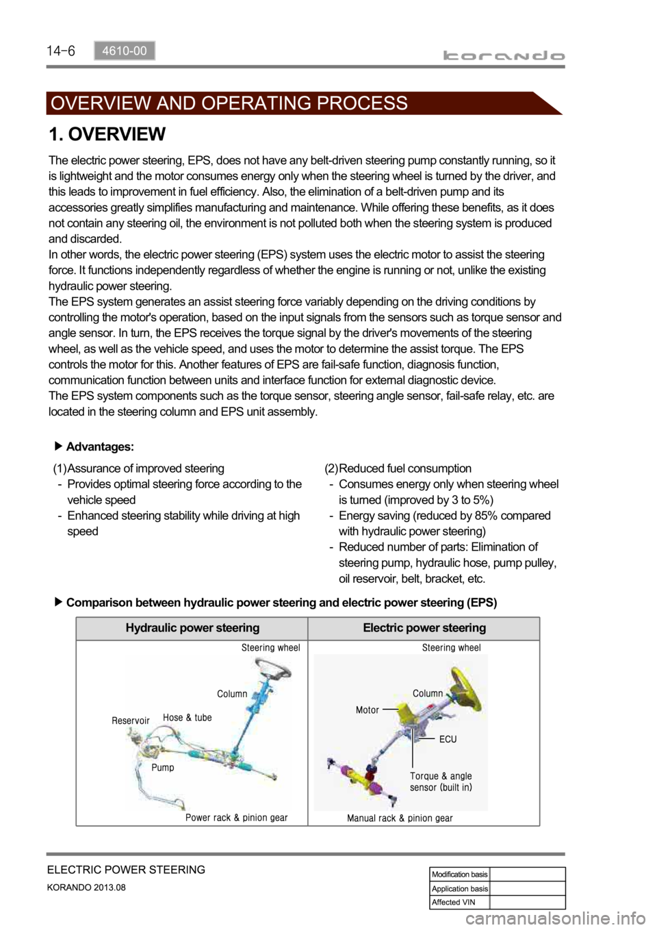
Hydraulic power steering Electric power steering
1. OVERVIEW
The electric power steering, EPS, does not have any belt-driven steering pump constantly running, so it
is lightweight and the motor consumes energy only when the steering wheel is turned by the driver, and
this leads to improvement in fuel efficiency. Also, the elimination of a belt-driven pump and its
accessories greatly simplifies manufacturing and maintenance. While offering these benefits, as it does
not contain any steering oil, the environment is not polluted both when the steering system is produced
and discarded.
In other words, the electric power steering (EPS) system uses the electric motor to assist the steering
force. It functions independently regardless of whether the engine is running or not, unlike the existing
hydraulic power steering.
The EPS system generates an assist steering force variably depending on the driving conditions by
controlling the motor's operation, based on the input signals from the sensors such as torque sensor and
angle sensor. In turn, the EPS receives the torque signal by the driver's movements of the steering
wheel, as well as the vehicle speed, and uses the motor to determine the assist torque. The EPS
controls the motor for this. Another features of EPS are fail-safe function, diagnosis function,
communication function between units and interface function for external diagnostic device.
The EPS system components such as the torque sensor, steering angle sensor, fail-safe relay, etc. are
located in the steering column and EPS unit assembly.
Advantages:
Assurance of improved steering
Provides optimal steering force according to the
vehicle speed
Enhanced steering stability while driving at high
speed (1)
-
-Reduced fuel consumption
Consumes energy only when steering wheel
is turned (improved by 3 to 5%)
Energy saving (reduced by 85% compared
with hydraulic power steering)
Reduced number of parts: Elimination of
steering pump, hydraulic hose, pump pulley,
oil reservoir, belt, bracket, etc. (2)
-
-
-
Comparison between hydraulic power steering and electric power steering (EPS)
Page 1158 of 1336

1. OVERVIEW
A radial tire uses a cord angle of 90 degrees. That is, the cord material runs in a radial or direct line from
one bead to the other across the tread. In addition, a radial tire has a belt overwrap under the tread
surface to provide greater structural stability. The belt overwrap of a radial tire distortion while the radial
structure enables high speed driving.
Tire supports the weight of the vehicle, reduces the impact from the road and at the same time,
transmits the power to propel, brake and steer on the road. It also functions to maintain a
vessel of air.
There is wear limit mark on the tire, which protrudes as a strip shape located approximately 1.6 mm from
mark on the shoulder to let the driver find the wear mark easily. To measure the tire groove depth,
measure at any point other than the point which has a wear limit mark.
The tire is worn unevenly according to the driver's driving habit, improper servicing, low tire inflation
pressure, changed tire location, etc.
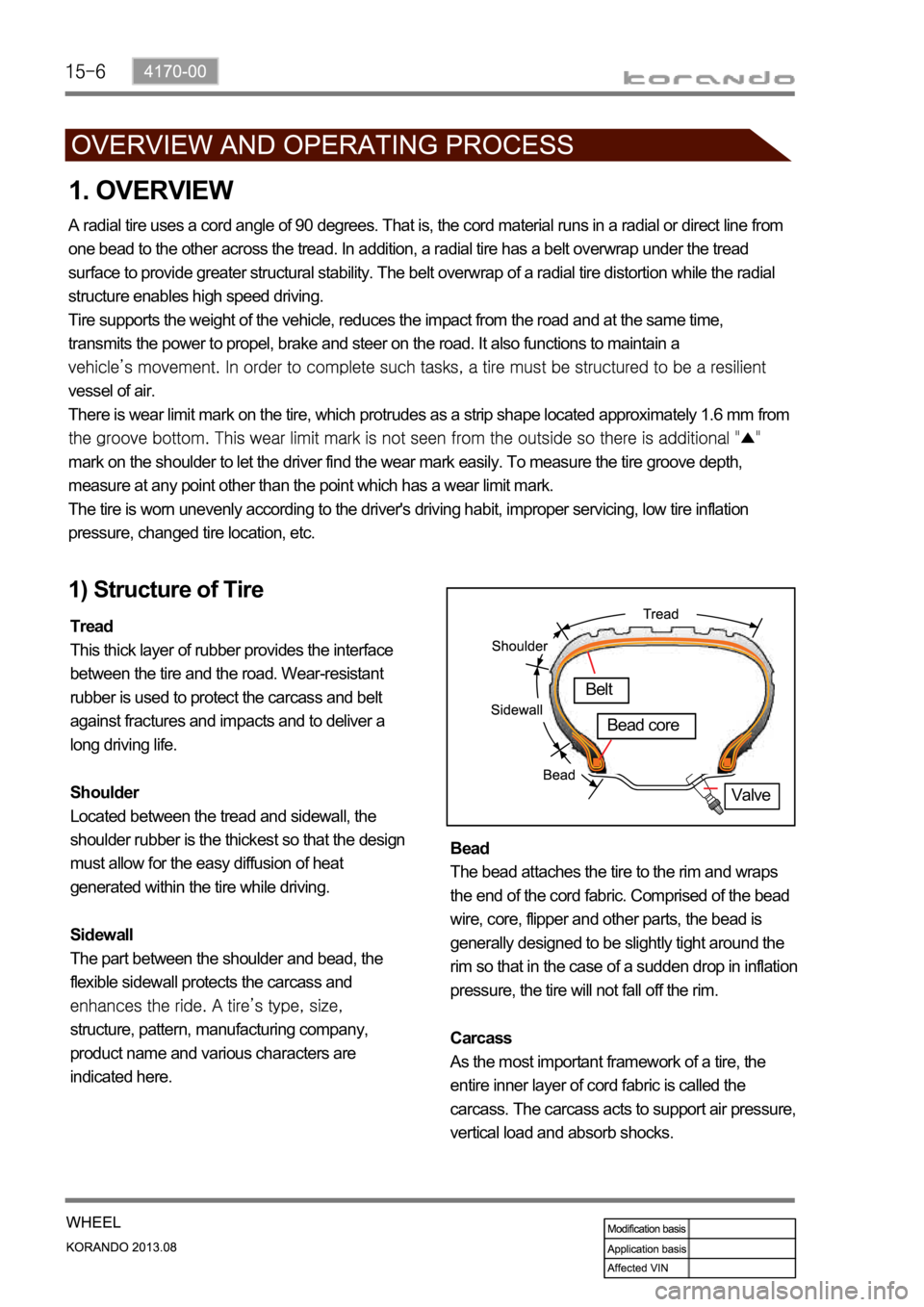
1) Structure of Tire
Tread
This thick layer of rubber provides the interface
between the tire and the road. Wear-resistant
rubber is used to protect the carcass and belt
against fractures and impacts and to deliver a
long driving life.
Shoulder
Located between the tread and sidewall, the
shoulder rubber is the thickest so that the design
must allow for the easy diffusion of heat
generated within the tire while driving.
Sidewall
The part between the shoulder and bead, the
flexible sidewall protects the carcass and
structure, pattern, manufacturing company,
product name and various characters are
indicated here. Bead
The bead attaches the tire to the rim and wraps
the end of the cord fabric. Comprised of the bead
wire, core, flipper and other parts, the bead is
generally designed to be slightly tight around the
rim so that in the case of a sudden drop in inflation
pressure, the tire will not fall off the rim.
Carcass
As the most important framework of a tire, the
entire inner layer of cord fabric is called the
carcass. The carcass acts to support air pressure,
vertical load and absorb shocks.
Valve
Belt
Bead core
Page 1226 of 1336

8810-00
1. SPECIFICATIONS
Item Item Specification
Air bag unit (SDM)Voltage range 8.0 V to 16.0 V
Voltage for system diagnosis and
SDM self diagnosis8.0 V to 16.0 V
Voltage for communication
between front and side impact
sensors7.0 V to 16.0 V
Storage temperature
Operating temperature
Air bag module and seat belt
pretensioner0.4 A for 10 seconds
1.2 A for 2 ms
Front and side impact sensorsOperating temperature
Power voltage 5.0 to 11.0 V
Measurement range 5.0 to 11.0 V
Contact CoilRated voltage 12.0 V
Voltage range 9.0 V to 16.0 V
Air bag circuit resistance
Current capacity 5.0 A
Rotation 2.1 rotations for each (LH/RH)
direction
Replacement interval Change at every 10 years
Page 1229 of 1336

3. CAUTIONS FOR AIR BAG SYSTEM
Cautions for air bag maintenance
Whenever installing or removing the devices related to the air bag system, disconnect the negative
battery cable and wait for at least 30 seconds.
Do not connect a tester probe to the inflator to measure the resistance of the component of the air
bag system. The detonator of the inflator may explode due to a sudden extra power supplied by the
tester.
Note that the used components related to the air bag system, especially the air bag unit, should be
packed in an air tight container and prevent it from any impact or damage.
When there is any deployed air bag (including curtain air bag and seat belt pretensioner), the entire
system including the air bag unit should be replaced. The deployed air bag unit should not be reused
since it has status data when it is deployed, and the data cannot be cleared with a diagnostic device.
The air bag and seat belt pretensioner systems contain explosive charges, so handle carefully when
disposing or replacing them. 1.
2.
3.
4.
5.
Cautions for air bag maintenance
Do not modify, change or apply impact on any air bag component. The air bag may be deployed
abruptly, causing serious injuries.
Children and infants should ride in a rear seat. Seating in the passenger seat with carrying a
child or infant is strictly prohibited. An infant or a child could be severely injured by the air bag
deployment.
A child restraint system must not be installed on the front seat. An infant or a child could be severely
injured by the air bag deployment when it is fitted to the passenger seat.
Do not place any objects on the air bag inflation location. You may get injured by those objects during
deployment.
Never put your arms around the front seat from behind, lean on the front seatback, or put your arms
out of the window. You can severely injured when the side air bag deploys.
Never lean on the door since it becomes very dangerous when the side air bag deploys.
The side air bag deploys when there is a severe side collision.
Do not slam the front door to close it. The side air bag may deploy unexpectedly.
When an occupant fastens the seat belt in an unstable or inclined posture, the air bag system cannot
protect the occupant properly. Moreover, the occupant can be injured by the air bag.
Do not move your seat too close to the steering wheel or dashboard. Being too close to the
steering wheel or instrument panel during the air bag deployment could cause serious injury,
including death
Hold only the outer rim of the steering so that the air bag can inflate without any hindrance.
Do not incline toward the steering wheel. Never allow the passenger to put hands or feet on the dash
board. The air bag cannot work properly Do not hold and operate the steering wheel by crossing your
arms You could get seriously injured when the air bag deploys. 1.
2.
3.
4.
5.
6.
7.
8.
9.
10.
11.
Page 1230 of 1336

8810-00
A large quantity of non-toxic gas (nitrogen gas) is generated with a loud noise when the air bag or
seat belt pretensioner deploys. If these airborne particles irritate your skin, eyes, nose, or throat, rinse
the area with cool water. If the irritation continues, see your doctor.
The windshield glass may be broken when the passenger air bag deploys.
The air bag is a unit to save an occupant's life from a sudden accident and it inflates at a very fast
speed by gas with high temperature, which might cause injury, such as an abrasion, bruise and burn
depending on the accident conditions.
The air bag components will be very hot after deployment. Do not touch them.
The deployed air bag/seat belt pretensioner cannot deploy again. It will work when an additional
impact is applied. Once the air bag system is triggered, the triggered air bag assembly should be
removed from the vehicle and replaced with a new one.
The air bag warning lamp is illuminated for 3 to 7 seconds after the engine is started to check
the system. If this warning lamp remains ON, then the system may be defective. Have the air
bag system checked immediately by Ssangyong Dealer or Ssangyong Authorized Service
Operation.
Incorrect inspection can result in serious injuries or malfunctions in the air bag and seat belt
pretensioner system. 12.
13.
14.
15.
16.
17.
18.