Page 563 of 1336

1490-00
3. ECU CONTROL
1) Functions
ECU receives and analyzes signals from various sensors and then modifies those signals into
permissible voltage levels and analyzes to control respective actuators.
ECU microprocessor calculates injection period and injection timing proper for engine piston speed and
crankshaft angle based on input data and stored specific map to control the engine power and emission
gas.
Output signal of the ECU microprocessor activates the injector solenoid valve to control the fuel injection
period and injection timing; so controls various actuators in response to engine changes.
Auxiliary function of ECU has adopted to reduce emission gas, improve fuel economy and enhance
safety, comforts and conveniences. For example, there are autocruise and immobilizer and adopted
CAN communication to exchange data among electrical systems (automatic T/M and brake system) in
the vehicle fluently. And the diagnostic tool can be used to diagnose vehicle status and defectives.
water and electromagnetism and there should be no mechanical shocks.
2) Control Functions
Controls by operating stages:
To make optimum combustion under every operating stage, ECU should calculate proper injection
volume in each stage by considering various factors.
Starting injection volume control:
During initial starting, injecting fuel volume will be calculated by function of temperature and engine
cranking speed. Starting injection continues from when the ignition switch is turned to ignition
position to till the engine reaches to allowable minimum speed.
Driving mode control:
If the vehicle runs normally, fuel injection volume will be calculated by accelerator pedal travel and
engine rpm and the drive map will be used to match the drivers inputs with optimum engine power. -
-
-
Page 564 of 1336
3) Injection Volume Control
(1) Overview
To keep the best engine conditions and to reduce the emission gas, ECU determines the injection
volume and timing.
(2) Components
Input Components
Accelerator pedal
position sensorFront oxygen
sensorCoolant temperature
sensorCrankshaft position
sensor
Camshaft position
sensorKnock sensorT-MAP sensorElectronic throttle
body
Output Components
Page 567 of 1336
0000-00
Coolant temperature
sensor
4) Ignition System Control
(1) Overview
G20DF engine is equipped with the single ignition system. Each spark plug is operated independently
by the ECU and one ignition coil and spark plug are provided for each cylinder.
(2) Components
Input Components
Crankshaft position
sensorAccelerator pedal position
sensor
Knock sensorCamshaft position
sensorElectronic
throttle body
Output Components
Page 569 of 1336

0000-00
(4) Features
Determines the ignition timing according to input signal
The ECU always analyzes the following elements when determining the ignition timing. 1.
Crankshaft position sensor
Camshaft position sensor
Coolant temperature sensor
Intake air temperature/air mass -
-
-
-
Warm-up of catalytic converter
The ignition timing is retarded for about 20 seconds to operate the catalytic converter according to the
operating temperature under the following conditions: 2.
The idle speed is increased by the idle speed control to help warming up of the catalytic converter -
-
Idle speed control
The ignition timing control can be performed faster than the control through the throttle valve.
Fuel cut-off in deceleration
The ignition timing is retarded temporarily to prevent abrupt increase of the torque when the
combustion is restarted.
Intake air temperature/coolant temperature
The ignition timing is retarded to prevent knocking if the intake air temperature or coolant temperature
is high. The ignition timing is retarded in the following cases. 3.
4.
5.
-
-
The ignition timing retard for intake air temperature and for coolant temperature is added up for
correction.
ESP/ASR control mode
The ignition timing is retarded to reduce engine torque as fast as possible under the ESP/ASR
control mode.
Knocking control
If knocking occurs in the cylinder, the ignition angle of the corresponding cylinder is retarded. The
6.
7.
Page 571 of 1336

0000-00
(2) Warm-up Control Function
Low voltage
If low voltage is detected by the ECU, the idle speed increases up to 100 rpm selectively under the
driving mode until the ignition switch is turned off. Idle speed control
The idle speed is controlled according to the fuel/air mixture when the engine load is changed, the
power steering wheel is turned to its end, the selector lever is in the "D" position and the A/C compresso
r
is in operation. It is also controlled according to the charge level during the purge control operation.
Ignition timing
The idle speed is controlled according to the fuel/air mixture when the engine load is changed, The
Air conditioner compressor operation
The air conditioner control unit sends the air conditioner operation signal to the ECU to increase the
throttle valve opening amount in order to prevent reduction of the engine speed when the air conditioner
compressor is in operation at idling.
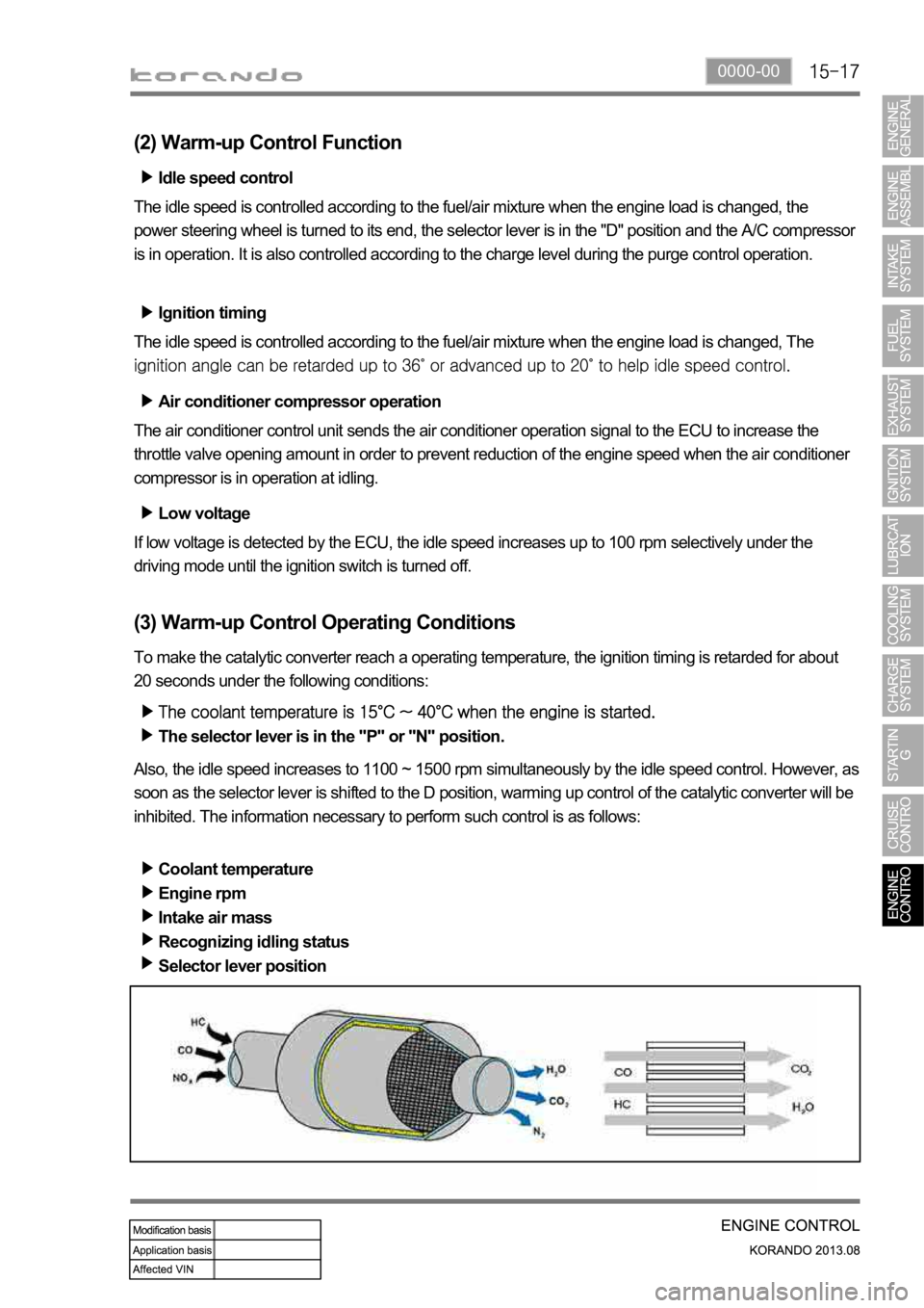
(3) Warm-up Control Operating Conditions
To make the catalytic converter reach a operating temperature, the ignition timing is retarded for about
20 seconds under the following conditions:
The selector lever is in the "P" or "N" position.
Also, the idle speed increases to 1100 ~ 1500 rpm simultaneously by the idle speed control. However, as
soon as the selector lever is shifted to the D position, warming up control of the catalytic converter will be
inhibited. The information necessary to perform such control is as follows:
Coolant temperature
Engine rpm
Intake air mass
Recognizing idling status
Selector lever position
Page 572 of 1336
6) Cooling Fan Control
(1) Overview of Cooling Fan and A/C Compressor
The cooling system maintains the engine temperature at an efficient level during all engine operating
conditions. The water pump draws the coolant from the radiator. The coolant then circulates through
water jackets in the engine block, the intake manifold, and the cylinder head. When the coolant reaches
the operating temperature of the thermostat, the thermostat opens. The coolant then goes back to the
radiator where it cools. The heat from automatic transaxle is also cooled down through the radiator by
circulating the oil through the oil pump. There are two cooling fans (180W+120W) in G20DF engine. ECU
controls the electric cooling fans with three cooling fan relays to improve the engine torque and air
conditioning performance.
(2) Components
Refrigerant pressure
sensorCoolant temperature
sensorG20DF Engine
ECURelay box in engine
compartment
A/C compressorCooling fan moduleT-MAP sensor
Page 574 of 1336
(4) Cooling Fan and A/C Compressor Control
Conditions for cooling fan
The cooling fan module controls the cooling fan relay, high speed relay and low speed relay.
The cooling fan is controlled by the series and parallel circuits
A/C
switchCooling
fanCoolant temperatureRefrigerant
pressureA/C
compressor
OFFOFF
-
LO
-
HI
-
ONLO
Refrigerant
pressure<18 bar
ON
HI
pressure
HI
-
HI
- OFF (cut)
A/C compressor OFF conditions
Approx. 4 seconds after starting the engine
When abrupt acceleration
Refrigerant pressure:
-
-
-
-
Output voltage according to refrigerant pressure
The output voltage from refrigerant pressure sensor is 1.7 V to 3.5 V when the refrigerant pressure is 10
Cooling fan control by ATF temperature
ATF temperature Cooling fan speed Remark
HI -
Page 575 of 1336
0000-00
7) Immobilizer Control
(1) Overview
The Immobilizer System provides an additional theft deterrent to the vehicle in which it is installed and
prevents it from being started by unauthorized persons. The transponder integrated in the key and the
engine control unit have the same code. When the ignition key with the integrated transponder is turned
to the ON position, the ECU (Engine Control Unit) checks the crypto code of the key and, if correct,
allows the vehicle to start the engine.
For details, refer to Chapter "BCM".
(2) Components
Conditions for cooling fan
Immobilizer
antenna
Immobilizer
key
Start motor
Instrument
cluster
BCM
G20DF ECU