Page 129 of 218
, make sure the tire
inflation pressure of all four tires is
correct.
i Restart the TPMS after adjusting")
X
Using the Tire and Loading Information
placard on the driver’s door B‑pillar
(Y page 128), make sure the tire
inflation pressure of all four tires is
correct.
i Restart the TPMS after adjusting the
tire inflation pressure to the inflation
pressure recommended for the vehicle
operating condition. Tire pressure
should only be adjusted on cold tires.
Observe the recommended tire inflation
pressure on the Tire and Loading
Informatio nplacard on the driver’s door
B‑pillar (Y page 128). X
Press Restarting TPMS button 0002.
The combination low tire pressure/TPMS
malfunction telltale in the instrument
cluster (Y page 21) flashes for
approximately 5 seconds and then goes
out.
After driving a few minutes the system
verifies that the current tire inflation
pressures are within the system’s
specified range. Afterwards the current
tire inflation pressures are accepted as
reference pressures and then monitored. Maximum tire inflation pressure
G
WARNING
Never exceed the max. tire inflation
pressure. Follow recommended tire
inflation pressures. Do not underinflate tires. Underinflated
tires wear excessively and/or unevenly,
adversely affect handling and energy
consumption, and are more likely to fail
from being overheated.
Do not overinflate tires. Overinflated
tires can adversely affect handling and
ride comfort, wear unevenly, increase
stopping distance, and result in sudden
deflation (blowout) because they are more
likely to become punctured or damaged by
road debris, potholes etc. i
For illustration purposes only. Actual
data on tires are specific to each vehicle
and may vary from data shown in above
illustration.
This is the maximum permissible tire
inflation pressure 0002for the tire.
Always follow the recommended tire
inflation pressure (Y page 122) for proper
tire inflation. Loading the vehicle
Two labels on your vehicle show how much
weight it may properly carry.
1) The Tire and Loading Information placard can be found on the driver’s
door B‑pillar. This placard tells you
important information about the
number of people that can be in the
vehicle and the total weight that can be
carried in the vehicle. It also contains
information on the proper size and Tires and wheels
127>> Operation. Z
Page 130 of 218
 The certification label, also found on the driver’s door B‑pillar, tells you
about the gross weight capaci")
recommended tire inflation pressures
for the original equipment tires on
your vehicle.
2) The certification label, also found on the driver’s door B‑pillar, tells you
about the gross weight capacity of your
vehicle, called the Gross Vehicle
Weight Rating (GVWR). The GVWR
includes the weight of the vehicle, all
occupants, automotive fluids and
cargo. The certification label also
tells you about the front and rear axle
weight capacity, called the Gross Axle
Weight Rating (GAWR). The GAWR is the
total allowable weight that can be
carried by a single axle (front or rear).
Never exceed the GVWR or GAWR for
either the front axle or rear axle. 0002
Driver’s door B‑pillar
Following is a discussion on how to work
with the information containe donthe Tire
and Loading Information placard with
regards to loading your vehicle.
Tire and Loading Information G
WARNING
Do not overload the tires by exceeding the
specified load limit as indicated on the
Tire and Loading Information placard on
the driver’s door B‑pillar. Overloading the
tires can overheat them, possibly causing
a blowout. Overloading the tires can also
result in handling or steering problems, or
brake failure. Tire and Loading Information placard
i
Data shown on Tire and Loading
Information placard example are for
illustration purposes only. Load limit
data are specific to each vehicle and may
vary from data shown in the following
illustration. Refer to Tire and Loading
Information placard on vehicle for
actual data specific to your vehicle. The Tire and Loading Information placard
showing load limit information 0002is
located on the driver’s door B‑pillar
(Y page 128).
X Locate the statement “The combined
weight of occupants and cargo should
never exceed XXXX kg or XXXX lbs.” on the
Tire and Loading Information placard.
The combined weight of all occupants and
cargo/luggage should never exceed the
weight referenced in that statement.
Seating capacity The seating capacity gives you important
information on the number of occupants128
Tires and wheels>> Operation.
Page 131 of 218
.
i Data shown on Tire and Loading
Informatio")
that can be in the vehicle. The Tire and
Loading Information placard showing
seating capacity 0002is located on the
driver’s door B‑pillar (Y page 128).
i Data shown on Tire and Loading
Information placard example are for
illustration purposes only .Seating
capacity data are specific to each
vehicle and may vary from data shown in
the following illustration. Refer to Tire
and Loading Information placard on
vehicle for actual data specific to your
vehicle.
Steps for determining correct load limit
The following steps have been developed as
required of all manufacturers under
Title 49, Code of U.S. Federal Regulations,
Part 575 pursuant to the “National Traffic
and Motor Vehicle Safety Act of 1966”.
X Step 1: Locate the statement “The
combined weight of occupants and cargo
should never exceed XXXX kg or
XXXX lbs.” on your vehicle’s Tire and
Loading Information placard.
X Step 2: Determine the combined weight of
the driver and passenger that will be
riding in your vehicle.
X Step 3: Subtract the combined weight of
the driver and passenger from
XXXX kilograms or XXXX lbs.
X Step 4: The resulting figure equals the
available amount of cargo and luggage
load capacity. For example, if the “XXXX”
amount equals 540 lbs and there will be
one 150 lbs passenger in your vehicle, the
amount of available cargo and luggage
load capacity is 390 lbs
(540 lbs - 150 lbs = 390 lbs).
X Step 5: Determine the combined weight of
luggage and cargo being loaded on the
vehicle. That weight may not safely
exceed the available cargo and luggage
load capacity calculated in step 4. i
The maximum cargo compartment load
is 110 lbs (50 kg).
The following table shows examples on how
to calculate total and cargo load
capacities with varying seating
configurations and number and size of
occupants. The following examples use a
load limit of 540 lbs. This is for
illustration purposes only . Make sure you
are using the actual load limit for your
vehicle stated on the vehicle’s Tire and
Loading Information placard (Y page 128).
The higher the weight of all occupants, the
less cargo and luggage load capacity is
available. Tires and wheels
129>> Operation. Z
Page 132 of 218

Examples for steps 1 to 3
Example 1 Example 2
Step 1 Combined weight limit of
occupants and cargo from Tire and
Loading Information placard
540 lbs 540 lbs
Step 2 Number of occupants (driver and
passenger)
2 1
Occupants weight
Occupant 1: 150 lbs
Occupant 2: 180 lbs Occupant 1: 150 lbs
Combined weight of all occupants
330 lbs 150 lbs
Step 3 Available cargo weight (total load
limit from Tire and Loading
Information placard minus
combined weight of all occupants)
540 lbs - 330 lbs =
210 lbs 540 lbs - 150 lbs =
390 lbs
Certification label
Even after careful determination of the
combined weight of all occupants and cargo
as to not exceed the permissible load
limit, you must make sure your vehicle
neve rexceed sthe Gross Vehicle Weight
Rating (GVWR) and the Gross Axle Weight
Rating (GAWR) for either the front or rear
axle. You can obtain the GVWR and GAWR
from the certification label. The
certification label can be found on the
driver’s door B‑pillar, see “Technical
data” (Y page 208).
Gross Vehicle Weight Rating (GVWR) means:
The total weight of the vehicle, all
occupants, and all cargo must never exceed
the GVWR.
Gross Axle Weight Rating (GAWR) means:
The total allowable weight that can be
carried by a single axle (front or rear).
To assur ethat your vehicle does not exceed
the maximum permissible weight limits
(GVWR and GAWR for front and rear axle),
have the loaded vehicle (including driver,
passenger, and all cargo) weighed on a
suitable commercial scale. Maximum tire load
G
WARNING
Do not overload the tires by exceeding the
specified load limit as indicated on the
Tire and Loading Information placard on
the driver’s door B‑pillar. Overloading the
tires can overheat them, possibly causing
a blowout. Overloading the tires can also
result in handling or steering problems, or
brake failure. i
For illustration purposes only. Actual
data on tires are specifi cto each vehicle
and may vary from data shown in above
illustration.
The maximum tire load 0002is the maximum
weight the tires are designed to support. 130
Tires and wheels>> Operation.
Page 133 of 218
.
For information on calculating total and
cargo load capacities (Y page 129).Direction of rotation
Unidirectional tires offer added
advantages, su")
For more information on tire load rating
(Y page 135).
For information on calculating total and
cargo load capacities (Y page 129).Direction of rotation
Unidirectional tires offer added
advantages, such as better hydroplaning
performance. To benefit ,however, you must
make sure the tires rotate in the direction
specified.
An arrow on the sidewall indicates the
intended direction of rotation (spinning)
of the tire. Tire care and maintenance
G
WARNING
Regularly check the tires for damage.
Damaged tires can cause tire inflation
pressure loss. As a result, you could lose
control of your vehicle.
Worn, old tires can cause accidents. If the
tire tread is badly worn, or if the tires have
sustained damage, replace them.
Check the tire inflation pressure at least
once a month. For more information on
checking tire inflation pressure, see
“Recommended tire inflation pressure”
(Y page 122).
Tire inspection Every time you check the tire inflation
pressure, you should also inspect your
tires for the following
R excessive treadwear (Y page 131)
R cord or fabric showing through the tire’s
rubber
R bumps, bulges, cuts, cracks or splits in
the tread or side of the tire
Replace the tire if you find any of the above
conditions. Life of tire G
WARNING
Tires should be replaced after 6 years,
regardless of the remaining tread.
The service life of atire is dependent upon
varying factors including but not limited
to
R driving style
R tire inflation pressure
R distance driven
Tread depth G
WARNING
Although the applicable federal motor
vehicle safety laws consider a tire to be
worn when the treadwear indicators (TWI)
become visible at approximately 1
/ 16 in
(1.6 mm), we recommend that you do not allow
your tires to wear down to that level. As
tread depth approaches 1
/ 8 in (3 mm), the
adhesion properties on a wet road are
sharply reduced.
Depending upon the weather and/or road
surface (conditions), the tire traction
varies widely.
Do not allow your tires to wear down too far.
Adhesion properties on wet roads are
sharply reduced at tread depths of less
than 1
/ 8 in (3 mm).
Treadwear indicators (TWI) are required by
law. These indicators are located in six
places on the tread circumference and
become visible at a tread depth of
approximately 1
/ 16 in (1.6 mm), at which
point the tire is considered worn and
should be replaced.
Recommended minimum tire tread depth:
Summer tires 1
/ 8 in (3 mm)
Winter tires 1
/ 6 in (4 mm) Tires and wheels
131>> Operation. Z
Page 134 of 218

Treadwear indicator
0002appears as a solid
band across the tread.
Storing tires !
Keep unmounted tires in a cool, dry
place with as little exposure to light as
possible. Protect tires from contact with
oil, grease and fuels.
Cleaning tires !
Never use a round nozzle to power wash
tires. The intense jet of water can result
in damage to the tire.
Always replace a damaged tire. Uniform Tire Quality Grading
Standards
The Uniform Tire Quality Grading is a U.S.
Government requirement designed to give
drivers consistent and reliable
information regarding tire performance.
Tire manufacturers are required to grade
tires based on three performance factors: treadwear
0002,traction 0003,and temperature
resistance 002B. Although not a Government
of Canada requirement, all tires made for
sale in North America have these grades
branded on the sidewall.
i For illustration purposes only. Actual
data on tires are specific to each vehicle
and may vary from data shown in above
illustration.
Quality grades can be found, where
applicable, on the tire sidewall between
trea dshoulder and maximum sectio nwidth.
For example: Treadwear Traction Temperature
200 AA A
All passenger car tires must conform to
federal safety requirements in addition to
these grades.
Treadwear The treadwear grade is a comparative
rating based on the wear rate of the tire
when tested under controlled condition
son
a specified U.S. government test course.
For example, a tire graded 150 would wear
one and one-half (1 1
/ 2 )t
imes as well on the
government course as a tire graded 100.
The relative performance of tires depends
upon the actual conditions of their use,
however, and may depart significantly from
the norm due to variations in driving
habits, service practices and differences
in road characteristics and climate.
Traction G
WARNING
The traction grade assigned to this tire is
based on straight-ahead braking traction
tests, and does not include acceleration,
cornering, hydroplaning, or peak traction
characteristics. 132
Tires and wheels>> Operation.
Page 135 of 218

The traction grades, from highest to
lowest, are AA, A, B, and C. Those grades
represent the tire’s ability to stop on wet
pavement as measured under controlled
conditions on specified government test
surfaces of asphalt and concrete. A tire
marked C may have poor traction
performance.
Temperature G
WARNING
The temperature grade for this tire is
established for a tire that is properly
inflated and not overloaded. Excessive
speed, underinflation, or excessive
loading, either separately or in
combination, can cause excessive heat
build-up and possible tire failure.
The temperature grades are A (the highest),
B, and C, representing the tire’s resistance
to the generation of heat and its ability to
dissipate heat when tested under
controlled conditions on a specified
indoor laboratory test wheel. Sustained
high temperature can cause the material of
the tire to degenerate and reduce tire life,
and excessive temperature can lead to
sudden tire failure. The grade C
corresponds to a level of performance
which all passenger car tires must meet
under the Federal Motor Vehicle Safety
Standard No. 109. Grades B and A represent
higher levels of performance on the
laboratory test wheel than the minimum
required by law. Rotating tires
G
WARNING
Do not rotate front and rear wheels as they
have different dimensions, e.g. rim size,
wheel offset etc. Otherwise, the handling
can be affected and you could endanger
yourself and others. Thoroughly clean the mounting face of the
wheels and brake discs, i.e. the inner side
of the wheels/tires each time the wheels/
tires are changed. Check for and ensure
proper tire inflation pressure. G
WARNING
Have the tightening torque checked after
changing awheel. Wheels could become
loose if not tightened with a torque of
81 lb‑ft (110 Nm).
Only use genuine smart wheel bolts
specified for your vehicle’s rims.
For information on wheel change, see “Flat
tire” (Y page 180). Tire labeling
Besides tire name (sales designation) and
manufacturer name, a number of markings
can be found on a tire.
Following are some explanations for the
markings on your vehicle’s tires: 0002
Uniform Quality Grading Standards
(Ypage 132)
0003 DOT, Tire Identification Number (TIN)
(Ypage 136)
002B Maximum tire load (Y page 130)
002A Maximum tire inflation pressure
(Ypage 127) Tires and wheels
133>> Operation. Z
Page 136 of 218

0018 Tire size designation, load and speed
rating (Y page 134)
0019 Load identification (Y page 136)
001A Tire name
i For illustration purposes on")
0028
Manufacturer
0029 Tire ply material (Y page 137)
0018 Tire size designation, load and speed
rating (Y page 134)
0019 Load identification (Y page 136)
001A Tire name
i For illustration purposes only. Actual
data on tires are specific to each vehicle
and may vary from data shown in above
illustration.
For more information, see “Rims and
tires” (Y page 210).
Tire size designation, load and speed
rating 0002
Tire width
0003 Aspect ratio in %
002B Radial tire code
002A Rim diameter
0028 Tire load rating
0029 Tire speed rating
i For information purposes only. Actual
data on tires are specific to each vehicle
and may vary from data shown in above
illustration.
General:
Depending on the design standards used,
the tire size molded into the sidewall may
have no letter or aletter preceding the tire
size designation. No letter preceding the size designation
(as illustrated above): Passenger car tire
based on European design standards.
Letter “P” preceding the size designation:
Passenger car tire based on U.S. design
standards.
Letter “LT” preceding the size
designation: Light Truck tire based on U.S.
design standards.
Letter “T” preceding the size designation:
Temporary spare tires which are high
pressure compact spares designed for
temporary emergency use only.
Tire width
Tire width 0002indicates the nominal tire
width in mm.
Aspect ratio
Aspect ratio 0003is the dimensional
relationship between tire section height
and section width and is expressed as a
percentage. The aspect ratio is arrived at
by dividing section height by section
width.
Tire code
Tire code 002Bindicates the tire
construction type. The “R” stands for radial
tire type. Letter “D” means diagonal or
bias ply construction; letter “B” means
belted-bias ply construction.
At the tire manufacturer’s option, any tire
with a speed capability above 149 mph
(240 km/h) can include a “ZR” in the size
designation (for example: 245/40 ZR 18).
For additional information, see “Tire
speed rating” (Y page 135).
Rim diameter
Rim diameter 002Ais the diameter of the
bead seat, not the diameter of the rim edge.
Rim diameter is indicated in inches (in). 134
Tires and wheels>> Operation.
 1
1 2
2 3
3 4
4 5
5 6
6 7
7 8
8 9
9 10
10 11
11 12
12 13
13 14
14 15
15 16
16 17
17 18
18 19
19 20
20 21
21 22
22 23
23 24
24 25
25 26
26 27
27 28
28 29
29 30
30 31
31 32
32 33
33 34
34 35
35 36
36 37
37 38
38 39
39 40
40 41
41 42
42 43
43 44
44 45
45 46
46 47
47 48
48 49
49 50
50 51
51 52
52 53
53 54
54 55
55 56
56 57
57 58
58 59
59 60
60 61
61 62
62 63
63 64
64 65
65 66
66 67
67 68
68 69
69 70
70 71
71 72
72 73
73 74
74 75
75 76
76 77
77 78
78 79
79 80
80 81
81 82
82 83
83 84
84 85
85 86
86 87
87 88
88 89
89 90
90 91
91 92
92 93
93 94
94 95
95 96
96 97
97 98
98 99
99 100
100 101
101 102
102 103
103 104
104 105
105 106
106 107
107 108
108 109
109 110
110 111
111 112
112 113
113 114
114 115
115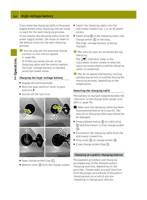 116
116 117
117 118
118 119
119 120
120 121
121 122
122 123
123 124
124 125
125 126
126 127
127 128
128 129
129 130
130 131
131 132
132 133
133 134
134 135
135 136
136 137
137 138
138 139
139 140
140 141
141 142
142 143
143 144
144 145
145 146
146 147
147 148
148 149
149 150
150 151
151 152
152 153
153 154
154 155
155 156
156 157
157 158
158 159
159 160
160 161
161 162
162 163
163 164
164 165
165 166
166 167
167 168
168 169
169 170
170 171
171 172
172 173
173 174
174 175
175 176
176 177
177 178
178 179
179 180
180 181
181 182
182 183
183 184
184 185
185 186
186 187
187 188
188 189
189 190
190 191
191 192
192 193
193 194
194 195
195 196
196 197
197 198
198 199
199 200
200 201
201 202
202 203
203 204
204 205
205 206
206 207
207 208
208 209
209 210
210 211
211 212
212 213
213 214
214 215
215 216
216 217
217