2013 SKODA ROOMSTER warning light
[x] Cancel search: warning lightPage 60 of 219
WARNING■The head restraints must be correctly adjusted in order to offer effective
protection for the occupants in the event of an accident.■
Never drive with the head restraints removed - risk of injury.
■
If the rear seats are occupied, the rear head restraint must not be in the
lower position.
headrest adjust
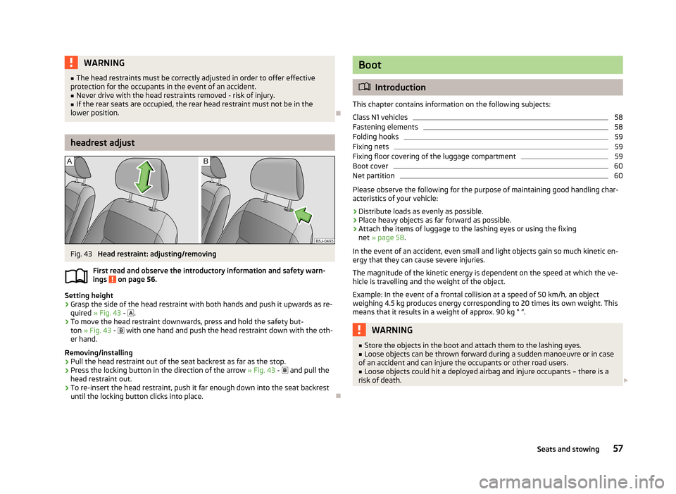
Fig. 43
Head restraint: adjusting/removing
First read and observe the introductory information and safety warn- ings
on page 56.
Setting height
›
Grasp the side of the head restraint with both hands and push it upwards as re-
quired » Fig. 43 -
.
›
To move the head restraint downwards, press and hold the safety but-
ton » Fig. 43 -
with one hand and push the head restraint down with the oth-
er hand.
Removing/installing
›
Pull the head restraint out of the seat backrest as far as the stop.
›
Press the locking button in the direction of the arrow » Fig. 43 -
and pull the
head restraint out.
›
To re-insert the head restraint, push it far enough down into the seat backrest until the locking button clicks into place.
Boot
Introduction
This chapter contains information on the following subjects:
Class N1 vehicles
58
Fastening elements
58
Folding hooks
59
Fixing nets
59
Fixing floor covering of the luggage compartment
59
Boot cover
60
Net partition
60
Please observe the following for the purpose of maintaining good handling char-
acteristics of your vehicle:
›
Distribute loads as evenly as possible.
›
Place heavy objects as far forward as possible.
›
Attach the items of luggage to the lashing eyes or using the fixing net » page 58 .
In the event of an accident, even small and light objects gain so much kinetic en-
ergy that they can cause severe injuries.
The magnitude of the kinetic energy is dependent on the speed at which the ve-
hicle is travelling and the weight of the object.
Example: In the event of a frontal collision at a speed of 50 km/h, an object
weighing 4.5 kg produces energy corresponding to 20 times its own weight. This
means that it results in a weight of approx. 90 kg “ ”.
WARNING■ Store the objects in the boot and attach them to the lashing eyes.■Loose objects can be thrown forward during a sudden manoeuvre or in case
of an accident and can injure the occupants or other road users.■
Loose objects could hit a deployed airbag and injure occupants – there is a
risk of death.
57Seats and stowing
Page 63 of 219
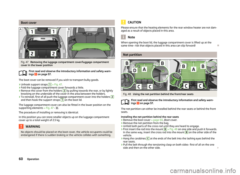
Boot coverFig. 47
Removing the luggage compartment cover/luggage compartment
cover in the lower position
First read and observe the introductory information and safety warn-
ings
on page 57.
The boot cover can be removed if you wish to transport bulky goods.
›
Unhook support straps
1
» Fig. 47 .
›
Fold the luggage compartment cover forwards a little.
›
Remove the cover from the holders
2
by pulling towards the rear, or by lightly
knocking on the underside of the cover in the area between the holders.
›
To reinstall, first of all push the luggage compartment cover into the holders
2
and then hook the support straps
1
on the boot lid.
The luggage compartment cover can also be fitted in the lower position on the
supporting elements » Fig. 47 -
.
The procedure of installing or removing is identical. In this position you can store smaller objects up on the luggage compartment cover up to a total weight of 2.5 kg.
WARNINGNo objects should be placed on the boot cover, the vehicle occupants could be
endangered if there is sudden braking or the vehicle collides with something.CAUTIONPlease ensure that the heating elements for the rear window heater are not dam-
aged as a result of objects placed in this area.
Note
When opening the boot lid, the luggage compartment cover is lifted up at the
same time- risk that objects placed in this area can slip forward!
Net partition
Fig. 48
Using the net partition behind the front/rear seats
First read and observe the introductory information and safety warn-
ings
on page 57.
The net partition can either be installed behind the rear seats or behind the front
seats.
Installing the net partition behind the rear seats
›
Remove the boot cover » page 60, Boot cover .
›
Remove the net partition from the bag.
›
Unfold both parts of the cross rod until they are heard to engage.
›
First insert the rod into the mount
B
» Fig. 48 on one side and push it forwards.
In the same way, insert the cross rod into the mount
B
on the other side of the
vehicle.
›
Hang the carabines
C
at the ends of the belt into the lashing eyes behind the
rear seats.
›
Pull the belt through the tensioning clasp on both sides- first of all on the one side and then on the other side.
60Operation
Page 68 of 219
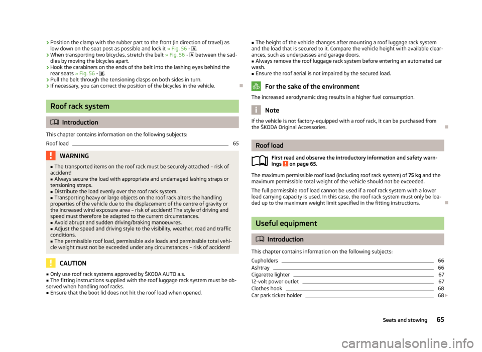
›Position the clamp with the rubber part to the front (in direction of travel) as
low down on the seat post as possible and lock it » Fig. 56 - .›
When transporting two bicycles, stretch the belt » Fig. 56 - between the sad-
dles by moving the bicycles apart.
›
Hook the carabiners on the ends of the belt into the lashing eyes behind the rear seats » Fig. 56 - .
›
Pull the belt through the tensioning clasps on both sides in turn.
›
If necessary, you can correct the position of the bicycles in the vehicle.
Roof rack system
Introduction
This chapter contains information on the following subjects:
Roof load
65WARNING■ The transported items on the roof rack must be securely attached – risk of
accident!■
Always secure the load with appropriate and undamaged lashing straps or
tensioning straps.
■
Distribute the load evenly over the roof rack system.
■
Transporting heavy or large objects on the roof rack alters the handling
properties of the vehicle due to the displacement of the centre of gravity or
the increased wind exposure area – risk of accident! The style of driving and
speed must therefore be adapted to the current circumstances.
■
Avoid abrupt and sudden driving/braking manoeuvres.
■
Adjust the speed and driving style to the visibility, weather, road and traffic
conditions.
■
The permissible roof load, permissible axle loads and permissible total vehi-
cle weight must not be exceeded under any circumstances – risk of accident!
CAUTION
■ Only use roof rack systems approved by ŠKODA AUTO a.s.■The fitting instructions supplied with the roof luggage rack system must be ob-
served when handling roof racks.■
Ensure that the boot lid does not hit the roof load when opened.
■ The height of the vehicle changes after mounting a roof luggage rack system
and the load that is secured to it. Compare the vehicle height with available clear- ances, such as underpasses and garage doors.■
Always remove the roof luggage rack system before entering an automated car
wash.
■
Ensure the roof aerial is not impaired by the secured load.
For the sake of the environment
The increased aerodynamic drag results in a higher fuel consumption.
Note
If the vehicle is not factory-equipped with a roof rack, it can be purchased from
the ŠKODA Original Accessories.
Roof load
First read and observe the introductory information and safety warn-
ings
on page 65.
The maximum permissible roof load (including roof rack system) of 75 kg and the
maximum permissible total weight of the vehicle should not be exceeded.
The full permissible roof load cannot be used if a roof rack system with a lower
load carrying capacity is used. In this case, the roof rack system must only be loa-
ded up to the maximum weight limit specified in the fitting instructions.
Useful equipment
Introduction
This chapter contains information on the following subjects:
Cupholders
66
Ashtray
66
Cigarette lighter
67
12-volt power outlet
67
Clothes hook
68
Car park ticket holder
68
65Seats and stowing
Page 70 of 219
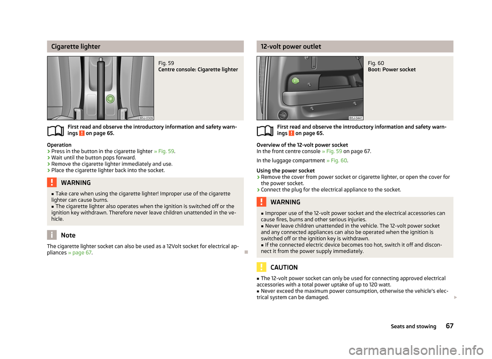
Cigarette lighterFig. 59
Centre console: Cigarette lighter
First read and observe the introductory information and safety warn-
ings on page 65.
Operation
›
Press in the button in the cigarette lighter » Fig. 59.
›
Wait until the button pops forward.
›
Remove the cigarette lighter immediately and use.
›
Place the cigarette lighter back into the socket.
WARNING■
Take care when using the cigarette lighter! Improper use of the cigarette
lighter can cause burns.■
The cigarette lighter also operates when the ignition is switched off or the
ignition key withdrawn. Therefore never leave children unattended in the ve-
hicle.
Note
The cigarette lighter socket can also be used as a 12Volt socket for electrical ap-
pliances » page 67 .
12-volt power outletFig. 60
Boot: Power socket
First read and observe the introductory information and safety warn-
ings on page 65.
Overview of the 12-volt power socket
In the front centre console » Fig. 59 on page 67.
In the luggage compartment » Fig. 60.
Using the power socket
›
Remove the cover from power socket or cigarette lighter, or open the cover for
the power socket.
›
Connect the plug for the electrical appliance to the socket.
WARNING■ Improper use of the 12-volt power socket and the electrical accessories can
cause fires, burns and other serious injuries.■
Never leave children unattended in the vehicle. The 12-volt power socket
and any connected appliances can also be operated when the ignition is switched off or the ignition key is withdrawn.
■
If the connected electric device becomes too hot, switch it off and discon-
nect it from the power supply immediately.
CAUTION
■ The 12-volt power socket can only be used for connecting approved electrical
accessories with a total power uptake of up to 120 watt.■
Never exceed the maximum power consumption, otherwise the vehicle's elec-
trical system can be damaged. 67Seats and stowing
Page 71 of 219
■If electrical consumers are switched on when the engine is not running, this will
cause the car battery to discharge – risk of battery discharge!■
Only use matching plugs to avoid damaging the 12-volt power socket.
■
Only use accessories that have been tested for electromagnetic compatibility in
accordance with the applicable directives.
■
Before turning the ignition on or off, and before starting the car, switch off the
device connected to the 12-volt power socket to prevent any damage caused by
voltage fluctuations.
■
Observe the operating instructions for the connected devices!
Clothes hook
First read and observe the introductory information and safety warn-ings
on page 65.
The clothes hooks are located on the handle of the headliner above each of therear doors.
WARNING■ Ensure that any clothes hanging from the hooks do not impair your vision to
the rear.■
Only use the hooks for hanging light items of clothing and ensure that there
are no heavy or sharp-edged objects in the pockets.
■
Do not use clothes hangers for hanging up items of clothing otherwise this
may reduce the effectiveness of head airbags.
CAUTION
The maximum permissible load of the hooks is 2 kg.
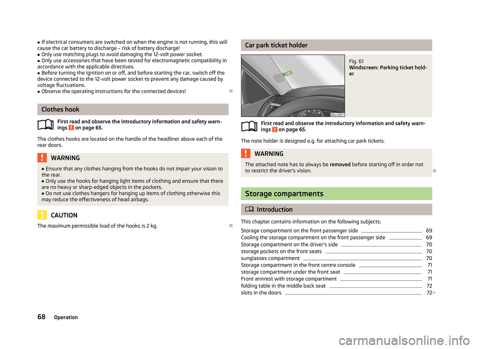
Car park ticket holderFig. 61
Windscreen: Parking ticket hold-
er
First read and observe the introductory information and safety warn-
ings on page 65.
The note holder is designed e.g. for attaching car park tickets.
WARNINGThe attached note has to always be removed before starting off in order not
to restrict the driver's vision.
Storage compartments
Introduction
This chapter contains information on the following subjects:
Storage compartment on the front passenger side
69
Cooling the storage compartment on the front passenger side
69
Storage compartment on the driver's side
70
storage pockets on the front seats
70
sunglasses compartment
70
Storage compartment in the front centre console
71
storage compartment under the front seat
71
Front armrest with storage compartment
71
folding table in the middle back seat
72
slots in the doors
72
68Operation
Page 73 of 219
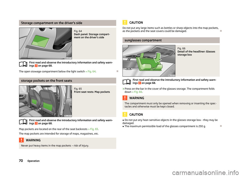
Storage compartment on the driver's sideFig. 64
Dash panel: Storage compart-
ment on the driver's side
First read and observe the introductory information and safety warn-
ings on page 68.
The open stowage compartment below the light switch » Fig. 64.
storage pockets on the front seats
Fig. 65
Front seat rests: Map pockets
First read and observe the introductory information and safety warn-
ings on page 68.
Map pockets are located on the rear of the seat backrests » Fig. 65.
The map pockets are intended for storage of maps, magazines, etc.
WARNINGNever put heavy items in the map pockets – risk of injury.CAUTIONDo not put any large items such as bottles or sharp objects into the map pockets,
as the pockets and the seat covers could be damaged.
sunglasses compartment
Fig. 66
Detail of the headliner: Glasses
storage box
First read and observe the introductory information and safety warn- ings on page 68.
›
Press on the bar in the cover of the glasses storage. The compartment folds down » Fig. 66 .
WARNINGThe compartment must only be opened when removing or inserting the spec-
tacles and otherwise must be kept closed.
CAUTION
■ Do not put any heat-sensitive objects in the glasses storage box - they may be
damaged.■
The maximum permissible load of the glasses compartment is 250 g.
70Operation
Page 76 of 219
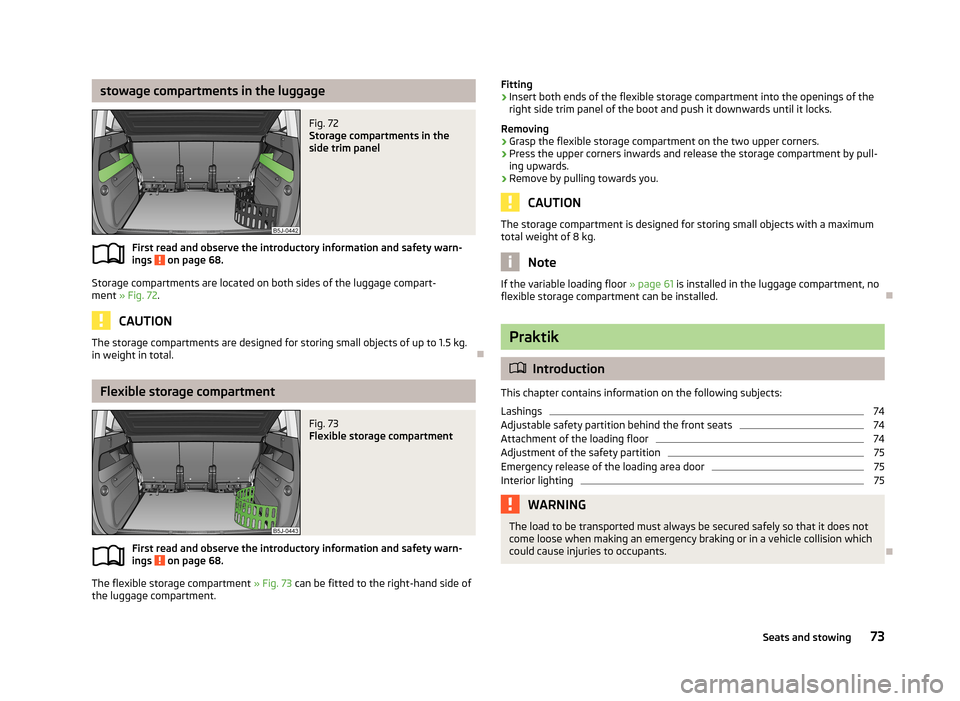
stowage compartments in the luggageFig. 72
Storage compartments in the
side trim panel
First read and observe the introductory information and safety warn-
ings on page 68.
Storage compartments are located on both sides of the luggage compart-
ment » Fig. 72 .
CAUTION
The storage compartments are designed for storing small objects of up to 1.5 kg.
in weight in total.
Flexible storage compartment
Fig. 73
Flexible storage compartment
First read and observe the introductory information and safety warn-
ings on page 68.
The flexible storage compartment » Fig. 73 can be fitted to the right-hand side of
the luggage compartment.
Fitting›Insert both ends of the flexible storage compartment into the openings of the
right side trim panel of the boot and push it downwards until it locks.
Removing›
Grasp the flexible storage compartment on the two upper corners.
›
Press the upper corners inwards and release the storage compartment by pull-
ing upwards.
›
Remove by pulling towards you.
CAUTION
The storage compartment is designed for storing small objects with a maximum
total weight of 8 kg.
Note
If the variable loading floor » page 61 is installed in the luggage compartment, no
flexible storage compartment can be installed.
Praktik
Introduction
This chapter contains information on the following subjects:
Lashings
74
Adjustable safety partition behind the front seats
74
Attachment of the loading floor
74
Adjustment of the safety partition
75
Emergency release of the loading area door
75
Interior lighting
75WARNINGThe load to be transported must always be secured safely so that it does not
come loose when making an emergency braking or in a vehicle collision which
could cause injuries to occupants.
73Seats and stowing
Page 83 of 219

We recommend that you leave the air outlet vents 3 » Fig. 80 on page 77 in the
open position in all operating modes.
Note
If the air distribution is set only to the windows, the entire volume of air is used
to defrost the windows and thus no air will be fed to the footwell. This can limit
the heating comfort.
Recirculated air mode
First read and observe the introductory information given on page 78.
Recirculated air mode prevents polluted air from outside the vehicle getting into
the vehicle, for example when driving through a tunnel or when standing in a
traffic jam.
Switching on/off
›
Press the
button.
The indicator light in the button lights up.
›
Press the
button again.
The indicator light in the button goes out.
Recirculated air mode is switched off automatically if the air distribution control
C
» Fig. 81 on page 79 is turned to the
position. Recirculated air mode can be
switched on again from this setting by pressing the
button again.
WARNINGNever leave recirculated air mode on over a longer period of time, as “stale air”
can cause fatigue of the driver and the passengers, reduce attention levels
and also cause the windows to mist up. The risk of having an accident increa-
ses. Switch off recirculated air mode as soon as the windows start to mist up.
Air conditioning system (manual air conditioning
system)
Introduction
This chapter contains information on the following subjects: Operation
81
Setting the air conditioning system
82
Recirculated air mode
82
The cooling system operates only if the following conditions are met. The cooling system is switched on » page 81.
The engine is running.
The outside temperature is above approximately +2 °C.
The blower switch is switched on (positions 1-4).
If the desired interior temperature can also be achieved without activating the cooling system, fresh air mode should be selected.
If the coolant temperature is too high, the cooling system is switched off to en-
sure that the engine cools down.
CAUTION
■ Under certain circumstances, air at a temperature of about 5 °C can flow out of
the vents when the cooling system is switched on.■
Lengthy and uneven distribution of the air flow out of the vents (especially
around the feet) and large differences in temperature, for example, when getting
out of the vehicle, can cause susceptible individuals to catch a cold.
Note
We recommend that you have the air conditioning system cleaned by a specialist
garage once every year.80Operation