Page 281 of 339

279
Emergencies
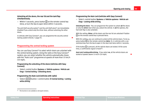
Anti-theft wheel bolts
Fig. 167 Anti-theft
wheel bolt with cap and
adapter
A special adapter (vehicle tools) is required to remove the anti-
theft wheel bolts.
– Remove the wheel cover* or the cap*.
– Insert the adapter onto the anti-theft wheel bolt and push it on
as far as it will go.
– Insert the wheel brace (vehicle tools) onto the adapter as far as
it will go.
– Remove the wheel bolt ⇒ page 279.
Note
Make a note of the code number of the anti-theft wheel bolt and keep it in a
safe place, but not in your vehicle. If you need a new adapter, you can ob-
tain it from the SEAT Official Service, indicating the code number.
Loosening the wheel bolts
Fig. 168 Wheel: loosen
the wheel bolts
– Insert the box spanner (vehicle tools) onto the wheel bolt as far
as it will go 1)
.
– Turn the wheel bolt approximately one turn to the left ⇒ Fig. 168
-arrow-. To apply the required torque, hold the wheel brace at
the end. If it is not possible to loosen a wheel bolt, carefully ap-
ply pressure with one foot on the end of the box spanner. Hold
on to the vehicle for support and take care not to slip.
1)
An adapter is required to unscrew or tighten the anti-theft wheel bolts ⇒ page 279.
Safety FirstOperating instructionsPractical TipsTechnical specifications
Page 282 of 339

280Emergencies
WARNING
Slightly loosen the wheel bolts (one turn) before raising the vehicle with
the jack*. If not, an accident may occur.
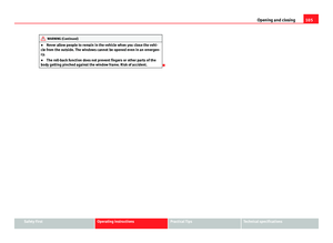
Raising the vehicle
Fig. 169 Crossbar:
marks
Fig. 170 Strut: mounting
the jack on the vehicle
– Place the jack* (vehicle tools) on a firm surface. If necessary use
a large, strong board or similar support. If the surface is slip-
pery (for example, tiles), use a non-slip base underneath the
jack (for example, a rubber mat) ⇒
.
– Find the support point on the strut (sunken area) closest to the
wheel to be changed ⇒ Fig. 169. The jack* support point is be-
hind the mark on the strut.
– Turn the jack*, located below the strut support point, to raise it
until tab A
⇒ Fig. 170 is below the housing provided.
– Align the jack* so that tab A
“grips” onto the housing provi-
ded on the longitudinal member and the mobile base plate B
is resting on the ground. The base plate B should fall vertically
with respect to the support point A.
– Continue turning the jack* until the wheel is slightly lifted off
the ground.
Page 283 of 339

281
Emergencies
WARNING
● Make sure that the jack* remains stable. If the surface is slippery or
soft, the jack* could slip or sink, respectively, with the resultant risk of
injury.
● Only raise the vehicle with the jack* supplied by the manufacturer.
Other vehicles could slip, with the consequent risk of injury.
● Only mount the jack* on the support points designed for this purpose
on the strut, and always align the jack correctly. If you do not, the jack*
could slip as it does not have an adequate grip on the vehicle: risk of in-
jury!
● The height of the parked vehicle can change as a result of variations
in temperature and loading.
CAUTION
The vehicle must not be raised on the crossbar. Only place the jack* on the
points designed for this purpose on the strut. Otherwise, the vehicle may be
damaged.
Removing and fitting a wheel
After loosening the wheel bolts and raising the vehicle with the
jack, change the wheel as described below:
Taking off the wheel
– Unscrew the wheel bolts using the box spanner and place them
on a clean surface.
– Take off the wheel ⇒
. Putting on the spare wheel
When fitting tyres with a compulsory rotation direction, observe
the instructions in
⇒ page 281.
– Mount the wheel.
– Screw on the wheel bolts in position and tighten them loosely
with a box spanner.
– Carefully lower the vehicle using the jack*.
– Tighten the wheel bolts in diagonal pairs using the wheel
brace.
The wheel bolts should be clean and turn easily. Before fitting the spare
wheel, inspect the wheel condition and hub mounting surfaces. These sur-
faces must be clean before fitting the wheel.
CAUTION
When removing/fitting the wheel, the rim may hit and damage the brake
disc. For this reason, please take care and get a second person to assist
you.
Tyres with compulsory direction of rotation
A directional tread pattern can be identified by arrows on the sidewall that
point in the direction of rotation. Always observe the direction of rotation in-
dicated when mounting the wheel. This is important so that these tyres can
give maximum grip and avoid excessive noise, tread wear and aquaplaning.
If, exceptionally, it is necessary to mount the spare wheel* in the opposite
direction of rotation, please drive carefully, as in this case the tyre does not
have optimum conditions of use. This is particularly important when driving
on wet roads.
Safety FirstOperating instructionsPractical TipsTechnical specifications
Page 284 of 339

282Emergencies
To benefit from the advantages of tyres with this type of tread pattern, the
defective tyre should be replaced as soon as possible so that all tyres again
rotate in the correct direction.
After changing a wheel
– On alloy wheels: replace the wheel bolt caps.
– On plate wheels: replace the wheel hubcap ⇒ page 278.
– Put the tools and jack back in the luggage compartment.
– If the replaced wheel does not fit in the spare wheel housing,
store it safely in the luggage compartment ⇒ page 17.
– Check the tyre pressure of the newly mounted tyre as soon as
possible.
– In vehicles fitted with a tyre pressure indicator, adjust the pres-
sure and store the reading in the radio/Easy Connect system*
⇒ page 214.
– The wheel bolts should be tightened to 120 Nm. Check the tor-
que as soon as possible with a torque wrench. Meanwhile, drive
carefully.
– Have the flat tyre replaced as quickly as possible. Spare wheel
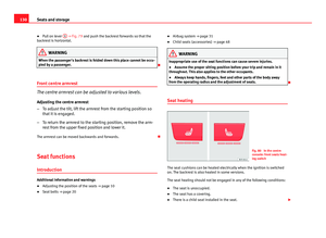
General information
Fig. 171 Compact tem-
porary spare wheel:
raised floor panel
The temporary spare wheel has been designed to be used for short
periods of time. Have the tyres checked, and if necessary, replaced
as soon as possible at a SEAT Official Service or at a specialised
workshop.
Please note the following restrictions when using the compact tem-
porary spare wheel. The compact temporary spare wheel is de-
signed specifically for this model. For this reason, do not use a
temporary spare wheel from a different type of vehicle.
Removing the temporary spare wheel
– Lift and hold up the floor panel to remove the temporary spare
wheel ⇒ Fig. 171.
– Turn the thumb wheel anti-clockwise.
Page 285 of 339

283
Emergencies
– Take out the temporary spare wheel.
Chains
For technical reasons, snow chains must not be used on the temporary
spare wheel.
If you have a puncture on one of the front wheels when using snow chains,
fit the temporary spare wheel in place of one of the rear wheels. Fit the snow
chains on the rear wheel that you have removed and replace the punctured
front wheel with this wheel.
WARNING
● After fitting the temporary spare wheel, check the tyre pressures as
soon as possible. Failure to do so may cause an accident. The tyre pres-
sures are listed on the inside of the fuel tank flap.
● Do not drive at over 80 km/h (50 mph) when the temporary spare
wheel is fitted on the vehicle: risk of accident!
● Avoid heavy acceleration, hard braking and fast cornering: risk of ac-
cident!
● Never use more than one temporary spare wheel at the same time,
risk of accident.
● No other type of tyre (normal summer or winter tyre) may be fitted on
the compact temporary spare wheel rim.
Extraction of the spare wheel in vehicles with SEAT SOUND
10 speakers (with subwoofer)*
– Disassemble the subwoofer’s floor panel (carpet) as follows:
– LEON / LEON SC model: first, pull the carpet in the direction of
the backrest and then pull the carpet upwards to remove it. LEON ST Model: lift and secure the luggage compartment floor
as explained in
⇒ page 148.
– Disconnect the subwoofer’s speaker cable.
– Turn the securing wheel anti-clockwise.
– Remove the subwoofer speaker and the spare wheel.
– When replacing the spare wheel, place the subwoofer speaker
in the direction indicated by the arrow and with the word
“FRONT” facing forward.
– Reconnect the speaker cable and firmly rotate the securing
wheel clockwise so that the subwoofer system and wheel are
firmly in place.
Jump starting Jump leads
The jump lead must have a sufficient wire cross section.
If the engine fails to start because of a discharged battery, the battery can
be connected to the battery of another vehicle to start the engine.
Jump leads
Jump leads must comply with standard DIN 72553 (see cable manufactur-
er's instructions). The wire cross section must be at least 25 mm 2
for petrol
engines and at least 35 mm 2
for diesel engines.
Safety FirstOperating instructionsPractical TipsTechnical specifications
Page 286 of 339

284Emergencies
Note
● The vehicles must not touch each other, otherwise electricity could flow
as soon as the positive terminals are connected.
● The discharged battery must be properly connected to the on-board net-
work.
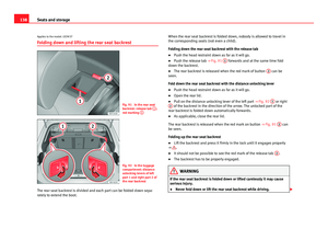
How to jump start: description
Fig. 172 Diagram of con-
nections for vehicles
without Start Stop sys-
tem
Fig. 173 Diagram of con-
nections for vehicles
with Start Stop system
Jump lead terminal connections
1. Switch off the ignition of both vehicles ⇒
.
2. Connect one end of the red jump lead to the positive +
termi-
nal of the vehicle with the flat battery A ⇒ Fig. 172.
3. Connect the other end of the red jump lead to the positive ter-
minal +
in the vehicle providing assistance B.
4. For vehicles without Start-Stop system: Connect one end of the
black jump lead to the negative terminal –
of the vehicle pro-
viding assistance B ⇒ Fig. 172.
– For vehicles with Start-Stop system: Connect one end of the
black jump lead X
to a suitable ground terminal, a solid piece
of metal in the engine block, or to the engine block ⇒ Fig. 173.
5. Connect the other end of the black jump lead X
to a solid met-
al component bolted to the engine block or to the engine block
itself of the vehicle with the flat battery. However, connect it to
a point as far as possible from the battery A
.
Page 287 of 339

285
Emergencies
6. Position the leads in such a way that they cannot come into contact with any moving parts in the engine compartment.
Starting
7. Start the engine of the vehicle with the boosting battery and let it run at idling speed.
8. Start the engine of the vehicle with the flat battery and wait two or three minutes until the engine is “running”.
Removing the jump leads
9. Before you remove the jump leads, switch off the dipped beam headlights (if they are switched on).
10.Turn on the heater blower and heated rear window in the vehi- cle with the flat battery. This helps minimise voltage peaks
which are generated when the leads are disconnected.
11.When the engine is running, disconnect the leads in reverse or- der to the details given above.
Connect the battery clamps so they have good metal-to-metal contact with
the battery terminals.
If the engine fails to start, switch off the starter after about 10 seconds and
try again after about half a minute.
WARNING
● Please note the safety warnings referring to working in the engine
compartment ⇒ page 251.
● The battery providing assistance must have the same voltage as the
flat battery (12V) and approximately the same capacity (see imprint on
battery). Failure to comply could result in an explosion.
● Never use jump leads when one of the batteries is frozen. Danger of
explosion! Even after the battery has thawed, battery acid could leak and
cause chemical burns. If a battery freezes, it should be replaced.
● Keep sparks, flames and lighted cigarettes away from batteries, dan-
ger of explosion. Failure to comply could result in an explosion.
● Observe the instructions provided by the manufacturer of the jump
leads.
● Do not connect the negative cable from the other vehicle directly to
the negative terminal of the flat battery. The gas emitted from the battery
could be ignited by sparks. Danger of explosion.
● Do not attach the negative cable from the other vehicle to parts of the
fuel system or to the brake line.
● The non-insulated parts of the battery clamps must not be allowed to
touch. The jump lead attached to the positive battery terminal must not
touch metal parts of the vehicle, this can cause a short circuit.
● Position the leads in such a way that they cannot come into contact
with any moving parts in the engine compartment.
● Do not lean on the batteries. This could result in chemical burns.
Note
The vehicles must not touch each other, otherwise electricity could flow as
soon as the positive terminals are connected.
Safety FirstOperating instructionsPractical TipsTechnical specifications
Page 288 of 339

286Emergencies
Towing and tow-starting the vehicle
General information
Points to observe when tow-starting or towing away If you use a tow rope:
Notes for the driver of the towing vehicle
– The tow rope must be taut before you drive off.
– Release the clutch very carefully when starting the vehicle
(manual gearbox), or accelerate gently (automatic gearbox).
Notes for the driver of the towed vehicle
– The ignition should be switched on so that the turn signals,
windscreen wipers and washers can be used. Please ensure
that the steering wheel is unlocked when you switch on the ig-
nition, and that it moves freely.
– Put the gearbox lever in neutral (manual gearbox) or move the
selector lever to position N (automatic gearbox).
– The brake servo only works when the engine is running. Consid-
erably more effort is required on the brake pedal when the en-
gine is switched off.
– Remember that the power steering only works when the ignition
is switched on and the vehicle is moving 1)
. Otherwise, consider-
ably more strength than usual will be required when steering. –
Ensure that the tow rope remains taut at all times.
Tow rope or tow bar
It is easier and safer to tow a vehicle with a tow bar. You should only use a
tow rope if you do not have a tow bar.
A tow rope should be slightly elastic to avoid damage to both vehicles. It is
advisable to use a tow rope made of synthetic fibre or similarly elastic mate-
rial.
Only attach the tow rope or the tow bar to the towing rings ⇒ page 287.
Driving style
Towing requires some experience, especially when using a tow rope. Both
drivers should be familiar with the technique required for towing. Inexper-
ienced drivers should not attempt to tow.
Do not pull too hard with the towing vehicle and take care to avoid jerking
the tow rope. When towing on an unpaved road, there is always a risk of
overloading and damaging the anchorage points.
WARNING
If the vehicle has no electrical power, the brake lights, turn signals and
all other lights will no longer function. Do not have the vehicle towed
away. Failure to do so could result in an accident.
CAUTION
If there is no oil in the gearbox or no lubricant in the automatic transmission
the car may only be towed with the driven wheels lifted clear of the road, or
transported on a special car transporter or trailer.
1)
Important: the battery must be correctly charged.