2013 RENAULT KANGOO fuel
[x] Cancel search: fuelPage 2 of 279

17B-2V2 MR-376-X76-17B050$010.mif
17B
V42 Injection
Program No.: 2A
Vdiag No.: 04, 05, 06,
14, 16, 18
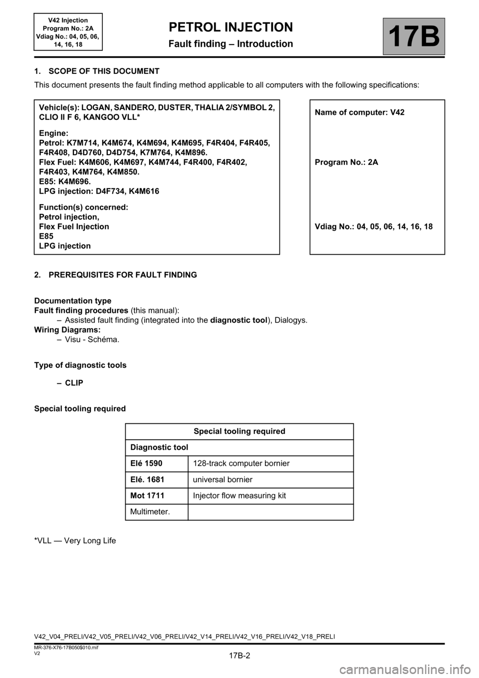
1. SCOPE OF THIS DOCUMENT
This document presents the fault finding method applicable to all computers with the following specifications:
2. PREREQUISITES FOR FAULT FINDING
Documentation type
Fault finding procedures (this manual):
– Assisted fault finding (integrated into the diagnostic tool), Dialogys.
Wiring Diagrams:
–Visu - Schéma.
Type of diagnostic tools
–CLIP
Special tooling required
*VLL — Very Long LifeVehicle(s): LOGAN, SANDERO, DUSTER, THALIA 2/SYMBOL 2,
CLIO II F 6, KANGOO VLL*Name of computer: V42
Engine:
Petrol: K7M714, K4M674, K4M694, K4M695, F4R404, F4R405,
F4R408, D4D760, D4D754, K7M764, K4M896.
Flex Fuel: K4M606, K4M697, K4M744, F4R400, F4R402,
F4R403, K4M764, K4M850.
E85: K4M696.
LPG injection: D4F734, K4M616Program No.: 2A
Function(s) concerned:
Petrol injection,
Flex Fuel Injection
E85
LPG injectionVdiag No.: 04, 05, 06, 14, 16, 18
Special tooling required
Diagnostic tool
Elé 1590128-track computer bornier
Elé. 1681universal bornier
Mot 1711Injector flow measuring kit
Multimeter.
V42_V04_PRELI/V42_V05_PRELI/V42_V06_PRELI/V42_V14_PRELI/V42_V16_PRELI/V42_V18_PRELI
PETROL INJECTION
Fault finding – Introduction
Page 5 of 279

17B-5V2 MR-376-X76-17B050$030.mif
17B
V42 Injection
Program No.: 2A
Vdiag No.: 04, 05, 06,
14, 16, 18
Injection computer:
The injection computer receives information from various sensors and sends control signals to various actuators
according to mappings that it has stored in the memory.
TDC sensor:
This sensor allows the computer to provide synchronisation as well as to know the position Top Dead Centre for
injection phasing.
Pinking sensor:
This sensor allows the computer to correct the ignition advance under high engine load to avoid damaging the
engine.
Refrigerant pressure sensor:
The role of the sensor is to measure the refrigerant fluid pressure in the air conditioning circuit.
Injection coolant temperature sensor:
The engine coolant temperature sensor informs the computer about the engine coolant temperature.
Injection air temperature sensor:
The air temperature sensor provides the computer with the temperature of air taken in by the engine.
Oxygen sensors:
The oxygen sensors allow the catalytic converter to correctly perform engine emission control tasks.
Accelerator potentiometer:
The potentiometer allows the computer to take into account driver requests expressed using the accelerator pedal.
Clutch pedal switch:
This switch allows the computer to convert to anti-jerking mode when the clutch pedal is depressed.
Brake light switch:
The brake light switch informs the computer of the brake pedal status.
Two gangs are used if the cruise control function exists.
Injectors:
These injectors enable rapid, precise metering of the quantity of fuel injected, with excellent injection process
repetitiveness.
PETROL INJECTION
Fault finding – Role of components
Page 7 of 279

17B-7V2 MR-376-X76-17B050$040.mif
17B
V42 Injection
Program No.: 2A
Vdiag No.: 04, 05, 06,
14, 16, 18
For flex-fuel engines
1. Air filter
2. Motorised throttle valve
3. Injection air temperature sensor
4. Manifold pressure
5. Injectors
6. Ignition coils
7. Injection coolant temperature sensor
8. Pinking sensor
9. TDC sensor
10. Upstream oxygen sensors
11. Downstream oxygen sensors
12. Injection computer
13. Auxiliary cold starting system
14. Auxiliary fuel tank
15. Auxiliary fuel
16. Petrol/alcohol tank
17. Petrol pump
18. Bleed valve
PETROL INJECTION
Fault finding – Operating diagram
Page 9 of 279

17B-9V2 MR-376-X76-17B050$050.mif
17B
V42 Injection
Program No.: 2A
Vdiag No.: 04, 05, 06,
14, 16, 18
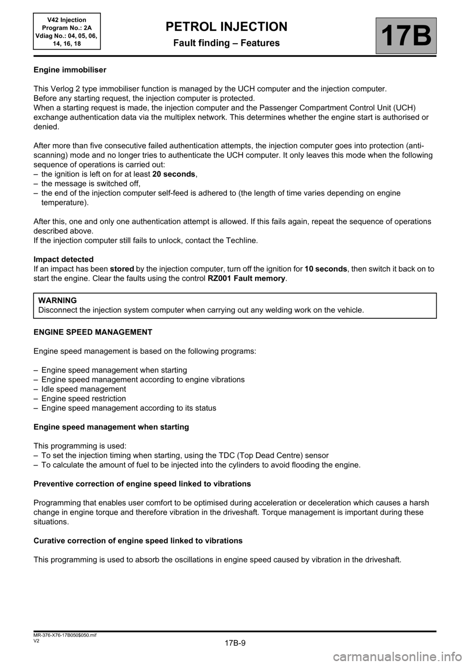
Engine immobiliser
This Verlog 2 type immobiliser function is managed by the UCH computer and the injection computer.
Before any starting request, the injection computer is protected.
When a starting request is made, the injection computer and the Passenger Compartment Control Unit (UCH)
exchange authentication data via the multiplex network. This determines whether the engine start is authorised or
denied.
After more than five consecutive failed authentication attempts, the injection computer goes into protection (anti-
scanning) mode and no longer tries to authenticate the UCH computer. It only leaves this mode when the following
sequence of operations is carried out:
– the ignition is left on for at least 20 seconds,
– the message is switched off,
– the end of the injection computer self-feed is adhered to (the length of time varies depending on engine
temperature).
After this, one and only one authentication attempt is allowed. If this fails again, repeat the sequence of operations
described above.
If the injection computer still fails to unlock, contact the Techline.
Impact detected
If an impact has been stored by the injection computer, turn off the ignition for 10 seconds, then switch it back on to
start the engine. Clear the faults using the control RZ001 Fault memory.
ENGINE SPEED MANAGEMENT
Engine speed management is based on the following programs:
– Engine speed management when starting
– Engine speed management according to engine vibrations
– Idle speed management
– Engine speed restriction
– Engine speed management according to its status
Engine speed management when starting
This programming is used:
– To set the injection timing when starting, using the TDC (Top Dead Centre) sensor
– To calculate the amount of fuel to be injected into the cylinders to avoid flooding the engine.
Preventive correction of engine speed linked to vibrations
Programming that enables user comfort to be optimised during acceleration or deceleration which causes a harsh
change in engine torque and therefore vibration in the driveshaft. Torque management is important during these
situations.
Curative correction of engine speed linked to vibrations
This programming is used to absorb the oscillations in engine speed caused by vibration in the driveshaft.WARNING
Disconnect the injection system computer when carrying out any welding work on the vehicle.
PETROL INJECTION
Fault finding – Features
Page 10 of 279

17B-10V2 MR-376-X76-17B050$050.mif
PETROL INJECTION
Fault finding – Features17B
V42 Injection
Program No.: 2A
Vdiag No.: 04, 05, 06,
14, 16, 18
Idle speed management
This programming is used to calculate the adapted idle speed according to the conditions of use (cold engine, air
conditioning requests, electrical consumer use etc.).
Air supply
This is managed by a motorised throttle valve which is controlled by the injection computer.
The injection computer also performs the following tasks using the motorised throttle:
– management of valve oscillations which can produce undesirable torque,
– management of valve movement subject to mechanical faults when the valve reaches its mechanical boundaries,
– management of acoustic faults by limiting throttle opening at a certain engine speed and when stopping the engine.
Torque management
The torque structure is the system for managing engine torque. It is necessary for some functions such as the
electronic stability program (ESP), automatic transmission (BVA) or sequential gearbox (BVR).
Each computer (ESP, sequential gearbox, automatic transmission) sends a request for torque via the multiplex
network to the injection computer. This arbitrates between the various torque requests and the driver's request
(made via the accelerator pedal or the cruise control/speed limiter).
The result of this arbitration gives the torque setpoint. The computer then calculates the throttle position setpoint, the
ignition advance and the wastegate setpoint (if a turbocharged engine) in order to provide the necessary torque.
Ignition management
Management of ignition advance enables the combustion quality to be managed and therefore engine operation to
be optimised. For a positive advance, the ignition point will be before TDC*, however the advance can have a
negative value.
TDC*: Top Dead Centre.
Fuel supply management
The fuel pump ensures the supply of fuel. It is activated for one second each time the + after ignition feed is switched
on. It ensures the correct level of pressure in the circuit and thereby achieves correct engine starting, particularly if
the vehicle has not been used for a long time. When the engine is running, the pump relay is controlled and
therefore the pump is always active.
The petrol vapour absorber enables petrol vapour to be collected in order to limit its release into the atmosphere.
Richness adjustment
Richness is managed using the upstream and downstream oxygen sensors located on the exhaust. For the sensors
to be operational quickly, they need to be heated by the exhaust gas and by a resistor internal to the sensor. These
sensors reflect the efficiency of combustion and, using information sent to the computer, they enable the quantity of
fuel injected to be managed in order to meet the emission control standards and to ensure optimum engine
operation.
Page 17 of 279

17B-17V2 MR-376-X76-17B050$070.mif
PETROL INJECTION
Fault finding – Fault summary table17B
V42 Injection
Program No.: 2A
Vdiag No.: 04, 05, 06,
14, 16, 18
*Info: InformationTool fault DTC code Diagnostic tool title
DF0810443 Canister bleed solenoid valve circuit
DF0820135 Upstream oxygen sensor heating circuit
DF0830141 Downstream oxygen sensor heating circuit
DF0850627 Fuel pump relay control circuit
DF0880325 Pinking sensor circuit
DF0910500 Vehicle speed signal
DF0920130 Upstream oxygen sensor circuit
DF0930136 Downstream oxygen sensor circuit
DF0950120 Throttle potentiometer circuit gang1
DF0960220 Throttle potentiometer circuit gang 2
DF101C121 ESP multiplex connection
DF1022503 Available alternator power sig.*
DF108C108 LPG/CNG computer multiplex connection
DF1090313 Low fuel level misfire
DF1200335 Engine speed sensor signal
DF1950016 Camshaft sensor / engine speed consistency
DF3190340 Camshaft sensor circuit
DF3420650 Malfunction indicator light circuit
DF3581608 Injector control computer
DF3611351 Ignition coil circuit 1-4
DF3621352 Ignition coil 2-3 circuit
DF3630011 Camshaft dephaser
DF37910A4 Cylinder injector 1 control
Page 18 of 279

17B-18V2 MR-376-X76-17B050$070.mif
PETROL INJECTION
Fault finding – Fault summary table17B
V42 Injection
Program No.: 2A
Vdiag No.: 04, 05, 06,
14, 16, 18
Tool fault DTC code Diagnostic tool title
DF38010A5 Cylinder 2 injector control
DF38110A6 Cylinder 3 injector control
DF38210A7 Cylinder injector 4 command
DF3940420 Catalytic converter operating fault
DF3980170 Fuel circuit operating fault
DF4090461 Fuel level sensor circuit
DF4361314 Detection of engine misfiring
DF4570315 Flywheel target
DF504C101 Automatic transmission
DF5310618 LPG system
DF5322502 Alternator charge signal
DF5562135 Pedal/throttle position consistency
DF6310703 Brake light switch signal
DF6331170 LPG fuel circuit operating fault
DF6351301 LPG cylinder 1 misfire
DF6361302 LPG cylinder 2 misfire
DF6371303 LPG cylinder 3 misfire
DF6381304 LPG cylinder 4 misfire
DF6391300 Combustion misfire in LPG mode
DF648060A Computer
DF7210217 Engine overheating
DF7732294 Pressure regulator circuit
Page 19 of 279

17B-19V2 MR-376-X76-17B050$070.mif
PETROL INJECTION
Fault finding – Fault summary table17B
V42 Injection
Program No.: 2A
Vdiag No.: 04, 05, 06,
14, 16, 18
*Refriger: RefrigerantTool fault DTC code Diagnostic tool title
DF8842632 Additional fuel circuit pump relay
DF8870226 Brake - accelerator pedal position
DF8941633 Additional fuel circuit solenoid valve
DF9740225 Pedal potentiometer circuit gang 1
DF9752120 Pedal potentiometer circuit gang 2
DF9921644 Additional heater 1 relay circuit
DF9931645 Additional heater 2 relay circuit
DF9941646 Additional heater 3 relay circuit
DF10150504 Brake switch signal consistency
DF10160833 Clutch switch signal consistency
DF1017061A Computer
DF10340314 Combustion misfire
DF10580106 Inlet pressure consistency
DF1063C415 ESP multiplex connection
DF10680530 Refriger* pressure sensor voltage
DF10720645 Air conditioning compressor relay control
DF10740638 Motorised throttle position inconsistent