2013 RENAULT KANGOO code fault
[x] Cancel search: code faultPage 185 of 279

17B-185V2 MR-376-X76-17B050$130.mif
PETROL INJECTION
Fault finding – Interpretation of parameters17B
V42 Injection
Program No.: 2A
Vdiag No.: 04, 05, 06,
14, 16, 18
AFTER REPAIRDeal with any faults displayed by the diagnostic tool.
Clear the computer memory.
Carry out a road test, then check with the diagnostic tool.
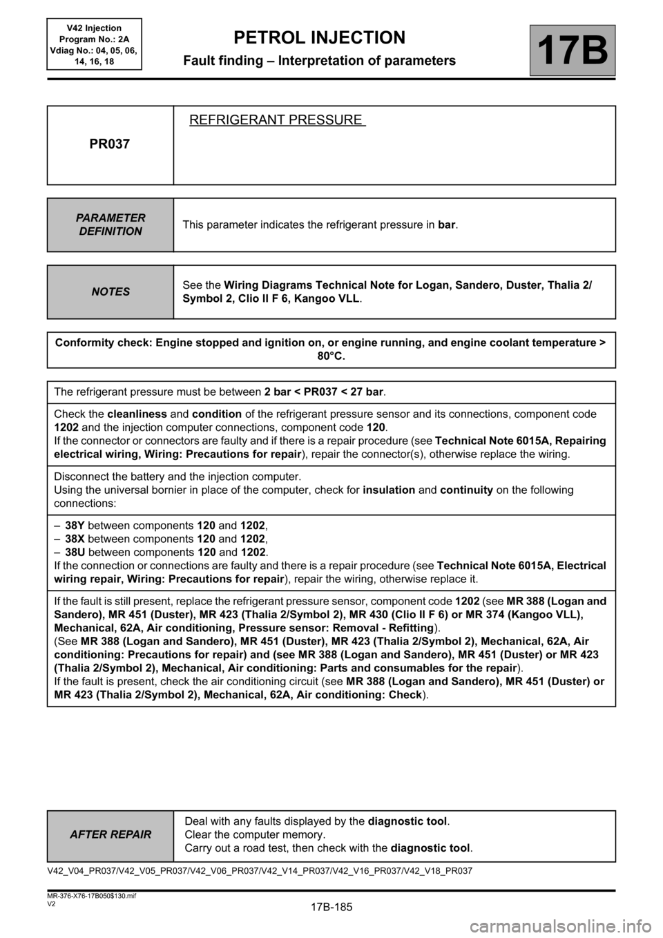
PR037REFRIGERANT PRESSURE
PA R A M E T E R
DEFINITIONThis parameter indicates the refrigerant pressure in bar.
NOTESSee the Wiring Diagrams Technical Note for Logan, Sandero, Duster, Thalia 2/
Symbol 2, Clio II F 6, Kangoo VLL.
Conformity check: Engine stopped and ignition on, or engine running, and engine coolant temperature >
80°C.
The refrigerant pressure must be between 2 bar < PR037 < 27 bar.
Check the cleanliness and condition of the refrigerant pressure sensor and its connections, component code
1202 and the injection computer connections, component code 120.
If the connector or connectors are faulty and if there is a repair procedure (see Technical Note 6015A, Repairing
electrical wiring, Wiring: Precautions for repair), repair the connector(s), otherwise replace the wiring.
Disconnect the battery and the injection computer.
Using the universal bornier in place of the computer, check for insulation and continuity on the following
connections:
–38Y between components 120 and 1202,
–38X between components 120 and 1202,
–38U between components 120 and 1202.
If the connection or connections are faulty and there is a repair procedure (see Technical Note 6015A, Electrical
wiring repair, Wiring: Precautions for repair), repair the wiring, otherwise replace it.
If the fault is still present, replace the refrigerant pressure sensor, component code 1202 (see MR 388 (Logan and
Sandero), MR 451 (Duster), MR 423 (Thalia 2/Symbol 2), MR 430 (Clio II F 6) or MR 374 (Kangoo VLL),
Mechanical, 62A, Air conditioning, Pressure sensor: Removal - Refitting).
(See MR 388 (Logan and Sandero), MR 451 (Duster), MR 423 (Thalia 2/Symbol 2), Mechanical, 62A, Air
conditioning: Precautions for repair) and (see MR 388 (Logan and Sandero), MR 451 (Duster) or MR 423
(Thalia 2/Symbol 2), Mechanical, Air conditioning: Parts and consumables for the repair).
If the fault is present, check the air conditioning circuit (see MR 388 (Logan and Sandero), MR 451 (Duster) or
MR 423 (Thalia 2/Symbol 2), Mechanical, 62A, Air conditioning: Check).
V42_V04_PR037/V42_V05_PR037/V42_V06_PR037/V42_V14_PR037/V42_V16_PR037/V42_V18_PR037
Page 220 of 279

17B-220
AFTER REPAIRCarry out a road test, then check with the diagnostic tool.
V2 MR-376-X76-17B050$160.mif
PETROL INJECTION
Fault finding – Fault Finding Chart17B
V42 Injection
Program No.: 2A
Vdiag No.: 04, 05, 06,
14, 16, 18
ALP 1 No dialogue with the computer
NOTESSee the Wiring Diagrams Technical Note for Logan, Sandero, Duster, Thalia 2/
Symbol 2, Clio II F 6, Kangoo VLL.
Try to establish dialogue with a computer on another vehicle to make sure that the diagnostic tool is not faulty. If
the tool is not the cause and communication cannot be established with any other computer on the same vehicle,
it is possible that another computer is disrupting the multiplex network.
Check the voltage of the battery.
If the battery voltage is between 9.5 V and 17.5 V, run fault finding on the charging circuit.
– Check the presence and condition of the injection fuses on the UPC and in the engine fuse box.
– Check the connection of the computer connectors, component code 120.
– Check the injection computer earths (quality, oxidation, tightness of the earth bolts on the battery terminal).
– Check that the supply to the computer is correct:
–Earth on connection NH of component 120 (for Logan, Sandero, Duster, Kangoo VLL),
–Earth on connection N of component 120 (for Thalia 2/Symbol 2),
–Earth on connection NF of component 120 (for Clio II F 6)
–+ 12V on connection 3FB of component 120.
If the connection(s) are faulty and there is a repair method (see Technical Note 6015A, Repairing electrical
wiring, Wiring: Precautions for repair), repair the wiring, otherwise replace it.
Check that the diagnostic socket, component code 225 is correctly supplied:
–+ before ignition feed on connection BP56 of component 225 (for Logan, Sandero, Duster),
–+ before ignition feed on connection BP10 of component 225 (for Thalia 2/Symbol 2, Clio II F 6, Kangoo
VLL),
–+ after ignition feed on connection AP10 of component 225,
– Earth on connections MAM and NC of component 225 (for Logan, Sandero, Duster
),
– Earth on connections N and M of component 225 (for Thalia 2/Symbol 2, Clio II F 6),
– Earth on connections NA and MK of component 225 (for Kangoo VLL).
If the connection(s) are faulty and there is a repair method (see Technical Note 6015A, Repairing electrical
wiring, Wiring: Precautions for repair), repair the wiring, otherwise replace it.
If dialogue has still not been established after these checks, contact the techline.
V42_V04_ALP1/V42_V05_ALP1/V42_V06_ALP1/V42_V14_ALP1/V42_V16_ALP1/V42_V18_ALP1
PETROL INJECTION
Fault finding – Fault Finding Chart
Page 251 of 279

17B-251
AFTER REPAIRCarry out a road test, then check with the diagnostic tool.
V2 MR-376-X76-17B050$180.mif
PETROL INJECTION
Fault finding – Tests17B
V42 Injection
Program No.: 2A
Vdiag No.: 04, 05, 06,
14, 16, 18
TEST 2 Alternator signal module check
NOTESSee the Wiring Diagrams Technical Note for Logan, Sandero, Duster, Thalia 2/
Symbol 2, Clio II F 6, Kangoo VLL.
With the engine running, check the alternator charge without any electrical consumers switched on using PR002
Alternator charge, then switch on the consumers and check the increase in PR002.
Check the cleanliness and condition of the alternator connector, component code 103 and of the injection
computer connector, component code 120.
If the connector or connectors are faulty and if there is a repair procedure (see Technical Note 6015A, Repairing
electrical wiring, Wiring: Precautions for repair), repair the connector(s), otherwise replace the wiring.
Check the insulation, continuity and the absence of interference resistance on the following connection.
–2K between components 103 and 120.
If the connection is faulty and if there is a repair procedure (see Technical Note 6015A, Electrical wiring repair,
Wiring: Precautions for repair), repair the wiring, otherwise replace the wiring.
If the check is correct, replace the alternator signal module, component code 103 (see MR 388 (Logan and
Sandero), MR 451 (Duster), MR 423 (Thalia 2/Symbol 2), MR 430 (Clio II F 6) or MR 374 (Kangoo VLL),
Mechanical, 16A, Starting - Charging, Alternator: Removal - Refitting).
If the fault is still present, contact the techline.
V42_V04_TEST2/V42_V05_TEST2/V42_V06_TEST2/V42_V14_TEST2/V42_V16_TEST2/V42_V18_TEST2
Page 253 of 279

17B-253
AFTER REPAIRCarry out a road test, then check with the diagnostic tool.
V2 MR-376-X76-17B050$180.mif
PETROL INJECTION
Fault finding – Tests17B
V42 Injection
Program No.: 2A
Vdiag No.: 04, 05, 06,
14, 16, 18
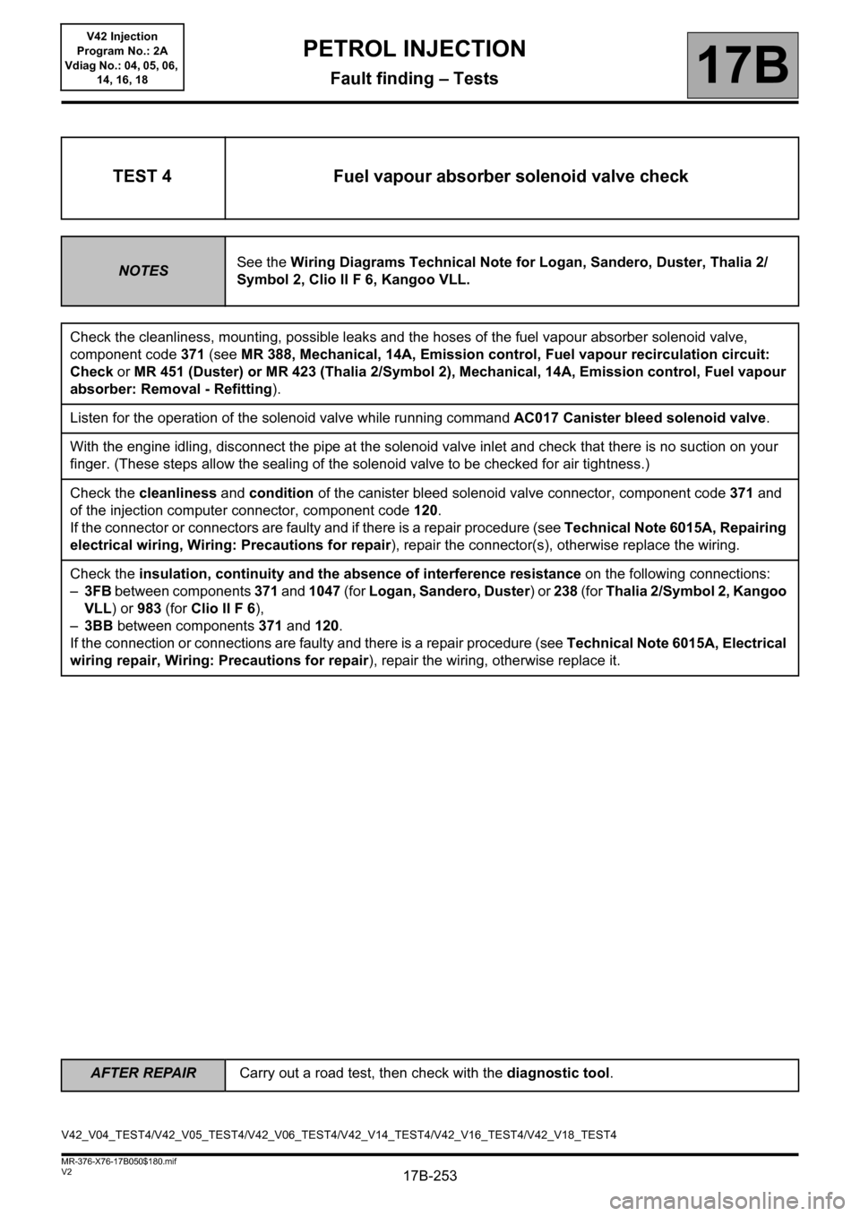
TEST 4 Fuel vapour absorber solenoid valve check
NOTESSee the Wiring Diagrams Technical Note for Logan, Sandero, Duster, Thalia 2/
Symbol 2, Clio II F 6, Kangoo VLL.
Check the cleanliness, mounting, possible leaks and the hoses of the fuel vapour absorber solenoid valve,
component code 371 (see MR 388, Mechanical, 14A, Emission control, Fuel vapour recirculation circuit:
Check or MR 451 (Duster) or MR 423 (Thalia 2/Symbol 2), Mechanical, 14A, Emission control, Fuel vapour
absorber: Removal - Refitting).
Listen for the operation of the solenoid valve while running command AC017 Canister bleed solenoid valve.
With the engine idling, disconnect the pipe at the solenoid valve inlet and check that there is no suction on your
finger. (These steps allow the sealing of the solenoid valve to be checked for air tightness.)
Check the cleanliness and condition of the canister bleed solenoid valve connector, component code 371 and
of the injection computer connector, component code 120.
If the connector or connectors are faulty and if there is a repair procedure (see Technical Note 6015A, Repairing
electrical wiring, Wiring: Precautions for repair), repair the connector(s), otherwise replace the wiring.
Check the insulation, continuity and the absence of interference resistance on the following connections:
–3FB between components 371 and 1047 (for Logan, Sandero, Duster) or 238 (for Thalia 2/Symbol 2, Kangoo
VLL) or 983 (for Clio II F 6),
–3BB between components 371 and 120.
If the connection or connections are faulty and there is a repair procedure (see Technical Note 6015A, Electrical
wiring repair, Wiring: Precautions for repair), repair the wiring, otherwise replace it.
V42_V04_TEST4/V42_V05_TEST4/V42_V06_TEST4/V42_V14_TEST4/V42_V16_TEST4/V42_V18_TEST4
Page 255 of 279

17B-255
AFTER REPAIRCarry out a road test, then check with the diagnostic tool.
V2 MR-376-X76-17B050$180.mif
PETROL INJECTION
Fault finding – Tests17B
V42 Injection
Program No.: 2A
Vdiag No.: 04, 05, 06,
14, 16, 18
TEST 5 Additional fuel tank check
NOTESSee the Wiring Diagrams Technical Note for Logan, Sandero, Duster, Thalia 2/
Symbol 2, Clio II F 6, Kangoo VLL.
Check the cleanliness, the mounting and for possible leaks of the hoses of the solenoid valve (see MR 388 (Logan
and Sandero), MR 451 (Duster), MR 423 (Thalia 2/Symbol 2), MR 430 (Clio II F 6) or MR 374 (Kangoo VLL),
Mechanical, 19C, Tank, Fuel pump of the additional fuel tank: Removal - Refitting).
Listen to the operation of the solenoid valve by running command AC217 Additional petrol circuit solenoid
valve.
Check the cleanliness and condition of the connector of the additional petrol circuit solenoid valve, component
code 1640 and the connector of the injection computer, component code 120.
If the connector or connectors are faulty and if there is a repair procedure (see Technical Note 6015A, Repairing
electrical wiring, Wiring: Precautions for repair), repair the connector(s), otherwise replace the wiring.
V42_V04_TEST5/V42_V05_TEST5/V42_V06_TEST5/V42_V14_TEST5/V42_V16_TEST5/V42_V18_TEST5
Page 256 of 279

17B-256
AFTER REPAIRCarry out a road test, then check with the diagnostic tool.
V2 MR-376-X76-17B050$180.mif
PETROL INJECTION
Fault finding – Tests17B
V42 Injection
Program No.: 2A
Vdiag No.: 04, 05, 06,
14, 16, 18
TEST 5
CONTINUED
Check the continuity, insulation, and absence of interference resistance on the following connections:
For Logan, Sandero, Duster:
–3ACM between components 1640 and 120,
–3FB between components 1640 and 1047,
For Thalia 2/Symbol 2, Kangoo VLL:
–3ACM between components 1640 and 120,
–3FB between components 1640 and 238,
For Clio II F 6:
–3ACM between components 1640 and 120,
–3FB between components 1640 and 983.
If the connection or connections are faulty and there is a repair procedure (see Technical Note 6015A, Electrical
wiring repair, Wiring: Precautions for repair), repair the wiring, otherwise replace it.
Check the supply of the solenoid valve using a test light, by running command AC224 Additional petrol circuit
pump relay.
Check the internal resistance of the solenoid valve, component code 1640 on the connector of the computer,
component code 120. Its value must be between: 24 < X 30 12 £ X £ 16 (Duster F4R engine) or 22
X 30
(Duster K4M engine) (between 0°C and 40°C). If the resistance is not correct, replace the solenoid
valve (see MR 388 (Logan and Sandero), MR 451 (Duster), MR 423 (Thalia 2/Symbol 2), MR 430 (Clio II F 6)
or MR 374 (Kangoo VLL), Mechanical, 19C, Tank, Fuel pump of the additional fuel tank: Removal -
Refitting).
If the fault is still present, contact the techline.
Page 258 of 279

17B-258
AFTER REPAIRCarry out a road test, then check with the diagnostic tool.
V2 MR-376-X76-17B050$180.mif
PETROL INJECTION
Fault finding – Tests17B
V42 Injection
Program No.: 2A
Vdiag No.: 04, 05, 06,
14, 16, 18
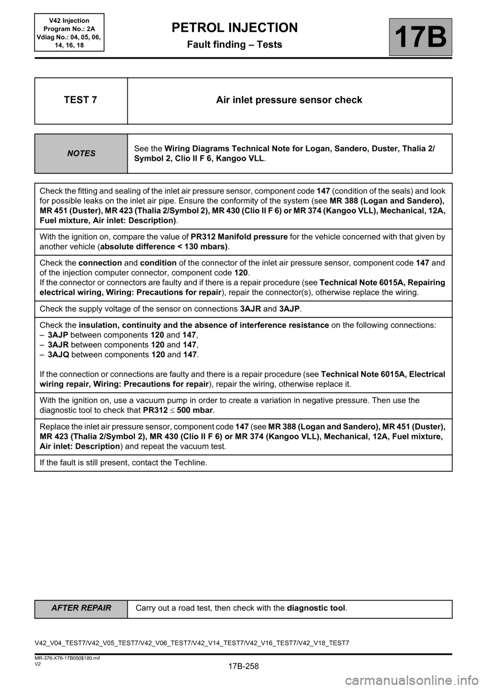
TEST 7 Air inlet pressure sensor check
NOTESSee the Wiring Diagrams Technical Note for Logan, Sandero, Duster, Thalia 2/
Symbol 2, Clio II F 6, Kangoo VLL.
Check the fitting and sealing of the inlet air pressure sensor, component code 147 (condition of the seals) and look
for possible leaks on the inlet air pipe. Ensure the conformity of the system (see MR 388 (Logan and Sandero),
MR 451 (Duster), MR 423 (Thalia 2/Symbol 2), MR 430 (Clio II F 6) or MR 374 (Kangoo VLL), Mechanical, 12A,
Fuel mixture, Air inlet: Description).
With the ignition on, compare the value of PR312 Manifold pressure for the vehicle concerned with that given by
another vehicle (absolute difference < 130 mbars).
Check the connection and condition of the connector of the inlet air pressure sensor, component code 147 and
of the injection computer connector, component code 120.
If the connector or connectors are faulty and if there is a repair procedure (see Technical Note 6015A, Repairing
electrical wiring, Wiring: Precautions for repair), repair the connector(s), otherwise replace the wiring.
Check the supply voltage of the sensor on connections 3AJR and 3AJP.
Check the insulation, continuity and the absence of interference resistance on the following connections:
–3AJP between components 120 and 147,
–3AJR between components 120 and 147,
–3AJQ between components 120 and 147.
If the connection or connections are faulty and there is a repair procedure (see Technical Note 6015A, Electrical
wiring repair, Wiring: Precautions for repair), repair the wiring, otherwise replace it.
With the ignition on, use a vacuum pump in order to create a variation in negative pressure. Then use the
diagnostic tool to check that PR312 500 mbar.
Replace the inlet air pressure sensor, component code 147 (see MR 388 (Logan and Sandero), MR 451 (Duster),
MR 423 (Thalia 2/Symbol 2), MR 430 (Clio II F 6) or MR 374 (Kangoo VLL), Mechanical, 12A, Fuel mixture,
Air inlet: Description) and repeat the vacuum test.
If the fault is still present, contact the Techline.
V42_V04_TEST7/V42_V05_TEST7/V42_V06_TEST7/V42_V14_TEST7/V42_V16_TEST7/V42_V18_TEST7
Page 260 of 279

17B-260
AFTER REPAIRCarry out a road test, then check with the diagnostic tool.
V2 MR-376-X76-17B050$180.mif
PETROL INJECTION
Fault finding – Tests17B
V42 Injection
Program No.: 2A
Vdiag No.: 04, 05, 06,
14, 16, 18
TEST 8
CONTINUED 1
Remove the accelerator pedal, component code 921 (see MR 388 (Logan and Sandero), MR 451 (Duster), MR
430 (Clio II F 6), MR 374 (Kangoo VLL), Mechanical, 17B, Petrol injection, Accelerator pedal potentiometer:
Removal - Refitting or MR 423 (Thalia 2/Symbol 2), Mechanical, 37A, Mechanical component controls,
Accelerator pedal: Removal - Refitting).
Without action on the accelerator pedal, check the resistance between the following connections (between 0°C
and 40ºC):
Gang 1:
–3LT and 3LS of component 921, the resistance must be between 718 X 5263 ,
–3LT and 3LR of component 921, the resistance must be between 838X1742,
–3LR and 3LS of component 921, the resistance must be between 1312X6495.
Gang 2:
–3LV and 3LW of component 921, the resistance must be between 701 X 5242
,
–3LV and 3LU of component 921, the resistance must be between 1495X3105,
–3LU and 3LW of component 921, the resistance must be between 1978X7894.
If these checks are incorrect, replace the accelerator pedal sensor, component code 921 (see MR 388 (Logan
and Sandero), MR 388 (Logan and Sandero), MR 451 (Duster), MR 430 (Clio II F 6), MR 374 (Kangoo VLL),
Mechanical, 17B, Petrol injection, Accelerator pedal potentiometer: Removal - Refitting or MR 423 (Thalia
2/Symbol 2), Mechanical, 37A, Mechanical component controls, Accelerator pedal: Removal - Refitting).
If the fault is still present, contact the Techline.