2013 Ram 1500 instrument cluster
[x] Cancel search: instrument clusterPage 101 of 196

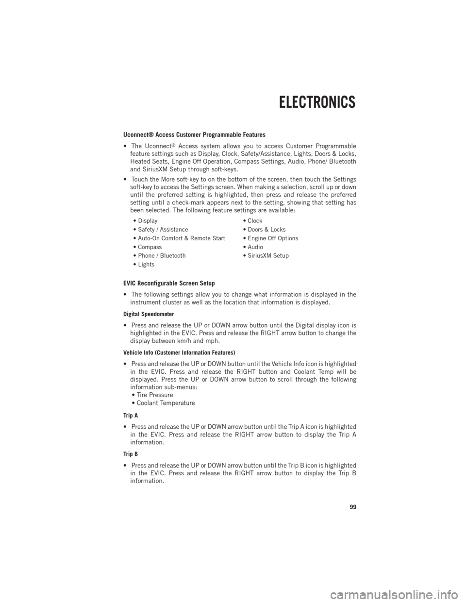
Uconnect® Access Customer Programmable Features
• The Uconnect
®Access system allows you to access Customer Programmable
feature settings such as Display, Clock, Safety/Assistance, Lights, Doors & Locks,
Heated Seats, Engine Off Operation, Compass Settings, Audio, Phone/ Bluetooth
and SiriusXM Setup through soft-keys.
• Touch the More soft-key to on the bottom of the screen, then touch the Settings soft-key to access the Settings screen. When making a selection, scroll up or down
until the preferred setting is highlighted, then press and release the preferred
setting until a check-mark appears next to the setting, showing that setting has
been selected. The following feature settings are available:
• Display • Clock
• Safety / Assistance • Doors & Locks
• Auto-On Comfort & Remote Start • Engine Off Options
• Compass • Audio
• Phone / Bluetooth • SiriusXM Setup
• Lights
EVIC Reconfigurable Screen Setup
• The following settings allow you to change what information is displayed in the instrument cluster as well as the location that information is displayed.
Digital Speedometer
• Press and release the UP or DOWN arrow button until the Digital display icon ishighlighted in the EVIC. Press and release the RIGHT arrow button to change the
display between km/h and mph.
Vehicle Info (Customer Information Features)
• Press and release the UP or DOWN button until the Vehicle Info icon is highlightedin the EVIC. Press and release the RIGHT button and Coolant Temp will be
displayed. Press the UP or DOWN arrow button to scroll through the following
information sub-menus:• Tire Pressure
• Coolant Temperature
Trip A
• Press and release the UP or DOWN arrow button until the Trip A icon is highlighted in the EVIC. Press and release the RIGHT arrow button to display the Trip A
information.
Trip B
• Press and release the UP or DOWN arrow button until the Trip B icon is highlightedin the EVIC. Press and release the RIGHT arrow button to display the Trip B
information.
ELECTRONICS
99
Page 102 of 196

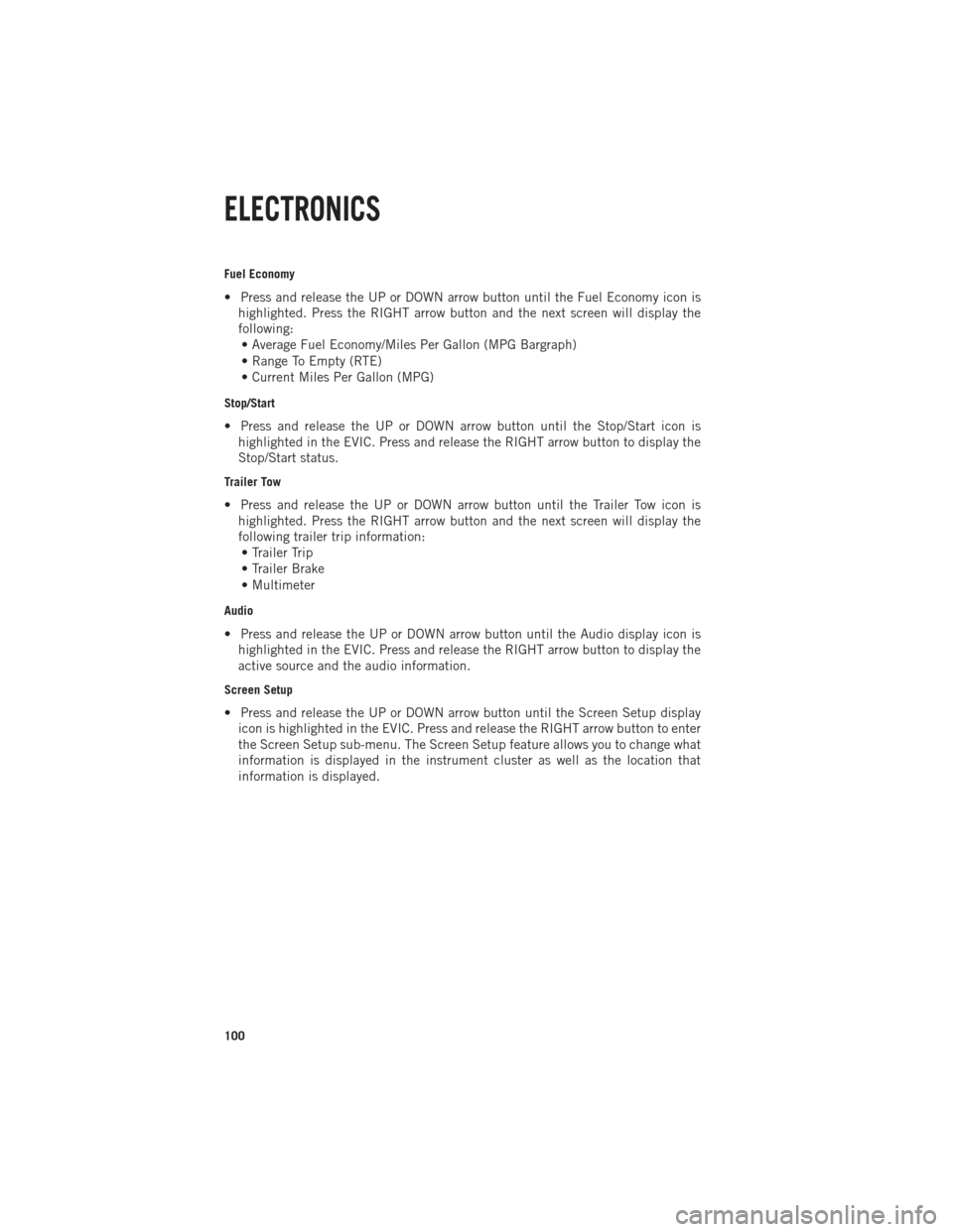
Fuel Economy
• Press and release the UP or DOWN arrow button until the Fuel Economy icon ishighlighted. Press the RIGHT arrow button and the next screen will display the
following:• Average Fuel Economy/Miles Per Gallon (MPG Bargraph)
• Range To Empty (RTE)
• Current Miles Per Gallon (MPG)
Stop/Start
• Press and release the UP or DOWN arrow button until the Stop/Start icon is highlighted in the EVIC. Press and release the RIGHT arrow button to display the
Stop/Start status.
Trailer Tow
• Press and release the UP or DOWN arrow button until the Trailer Tow icon ishighlighted. Press the RIGHT arrow button and the next screen will display the
following trailer trip information:• Trailer Trip
• Trailer Brake
• Multimeter
Audio
• Press and release the UP or DOWN arrow button until the Audio display icon is highlighted in the EVIC. Press and release the RIGHT arrow button to display the
active source and the audio information.
Screen Setup
• Press and release the UP or DOWN arrow button until the Screen Setup displayicon is highlighted in the EVIC. Press and release the RIGHT arrow button to enter
the Screen Setup sub-menu. The Screen Setup feature allows you to change what
information is displayed in the instrument cluster as well as the location that
information is displayed.
ELECTRONICS
100
Page 118 of 196

TOW/HAUL MODE
•When driving in hilly areas, towing a trailer, carrying a heavy load, etc., and frequent
transmission shifting occurs, press the TOW/HAUL switch to select TOW/HAUL
mode. This will improve performance and reduce the potential for transmission
overheating or failure due to excessive shifting. When operating in TOW/HAUL mode,
transmission upshifts are delayed, and the transmission will automatically downshift
(for engine braking) during steady braking maneuvers.
• The “TOW/HAUL Indicator Light” will illuminate in the instrument cluster to
indicate that TOW/HAUL mode has
been activated. Pressing the switch a
second time restores normal operation.
If the TOW/HAUL mode is desired, the
switch must be pressed each time the
engine is started.
INTEGRATED TRAILER BRAKE MODULE
• The Integrated Trailer Brake Controller allows you to automatically or manuallyactivate the Electric Trailer Brakes and Electric Over Hydraulic Trailer Brakes for a
better braking performance when towing a trailer.
NOTE:
The Integrated Trailer Brake Controller is located in the center stack below the
climate controls.
• This module will have four different options depending on the type of trailer you want to tow and can be selected through the Electronic Vehicle Information Center
(EVIC) or touch-screen radio – if equipped.• Light Electric
• Heavy Electric
• Light EOH (Electric Over Hydraulic)
• Heavy EOH (Electric Over Hydraulic)
UTILITY
116
Page 131 of 196

Adding Diesel Exhaust Fluid
• The DEF gauge (located in the instrument cluster) will display the level of DEFremaining in the tank.
NOTE:
Driving conditions (altitude, vehicle speed, load, etc.) will effect the amount of DEF
that is used in your vehicle.
NOTE:
Since DEF will begin to freeze at 12°F (-11°C), your vehicle is equipped with an
automatic DEF heating system. This allows the DEF injection system to operate
properly at temperatures below 12°F (-11°C). If your vehicle is not in operation for an
extended period of time with temperatures below 12°F (-11°C), the DEF in the tank
may freeze. If the tank is overfilled and freezes, it could be damaged. Therefore, do
not overfill the DEF tank. Extra care should be taken when filling with portable
containers to avoid overfilling. Note the level of the DEF gauge in your instrument
cluster. On pickup applications, you may safely add a maximum of 2 gallons of DEF
from portable containers when your DEF gauge is reading ½ full. On Chassis Cab
applications a maximum of 2 gallons may be added when the DEF gauge is reading
¾ full
DEF Fill Procedure
• Remove cap from DEF tank (located on drivers side of the vehicle).
• Insert DEF container into DEF tank.
• Reinstall cap onto DEF tank.
• Refer to your Owner's Manual on the DVD for further details.
CAUTION!
•To avoid DEF spillage and overfilling, do not “top off” the DEF tank after filling.•When DEF is spilled, clean the area immediately with water or a mild solvent.
DIESEL
129
Page 132 of 196

ROADSIDE ASSISTANCE
•Dial toll-free 1-800-521-2779 for U.S. Residents or 1-800-363-4869 for Canadian
Residents.
• Provide your name, vehicle identification number, license plate number, and your location, including the telephone number from which you are calling.
• Briefly describe the nature of the problem and answer a few simple questions.
• You will be given the name of the service provider and an estimated time of arrival. If you feel you are in an “unsafe situation”, please let us know. With your consent,
we will contact local police or safety authorities.
INSTRUMENT CLUSTER WARNING LIGHTS
- Electronic Stability Control (ESC) Activation/Malfunction Indicator Light
•
If this indicator light flashes during acceleration, apply as little throttle as possible.
While driving, ease up on the accelerator. Adapt your speed and driving to the
prevailing road conditions. To improve the vehicle's traction when starting off in deep
snow, sand or gravel, it may be desirable to switch the ESC system off.
- Tire Pressure Monitoring System (TPMS) Light
•
Each tire, including the spare (if provided), should be checked monthly, when cold
and inflated to the inflation pressure recommended by the vehicle manufacturer on
the vehicle placard or tire inflation pressure label. (If your vehicle has tires of a
different size than the size indicated on the vehicle placard or tire inflation pressure
label, you should determine the proper tire inflation pressure for those tires.)
• As an added safety feature, your vehicle has been equipped with a Tire Pressure Monitoring System (TPMS) which display in the Electronic Vehicle Information
Center (EVIC) when one or more of your tires is significantly under-inflated.
Accordingly, when the low tire pressure EVIC display illuminates, you should stop
and check your tires as soon as possible, and inflate them to the proper pressure.
Driving on a significantly under-inflated tire causes the tire to overheat and can
lead to tire failure. Under-inflation also reduces fuel efficiency and tire tread life,
and may affect the vehicle’s handling and stopping ability.
• IF THE LIGHT STARTS FLASHING INDICATING A LOW TIRE PRESSURE, ADJUST THE AIR
PRESSURE IN THE LOW TIRE TO THE AIR PRESSURE SHOWN ON THE VEHICLE PLACARD
OR TIRE INFLATION PRESSURE LABEL LOCATED ON THE DRIVER'S DOOR. NOTE: AFTER
INFLATION, THE VEHICLE MAY NEED TO BE DRIVEN FOR 20 MINUTES BEFORE THE
FLASHING LIGHT WILL TURN OFF.
•
Please note that the TPMS is not a substitute for proper tire maintenance, and it is
the driver’s responsibility to maintain correct tire pressure, even if under-inflation has
not reached the level to trigger illumination of the TPMS low EVIC display.
WHAT TO DO IN EMERGENCIES
130
Page 181 of 196

Cavity Cartridge Fuse Micro FuseDescription
F25 30 Amp Pink Front Wiper High Speed
F26 30 Amp Pink Antilock Brakes/Stability Control
Module/Valves
F28 20 Amp Yellow Trailer Tow Backup Lights –
If Equipped
F29 20 Amp Yellow Trailer Tow Parking Lights –
If Equipped
F30 30 Amp Pink Trailer Tow Receptacle
F32 30 Amp Pink Drive Train Control Module –
If Equipped
F33 20 Amp Yellow Diesel Fuel Heater #1 –
If Equipped / Rear Blower – If Equipped
F34 30 Amp Pink Vehicle System Interface
Module #2 – If Equipped
F35 30 Amp Pink Sunroof – If Equipped
F36 30 Amp Pink Rear Defroster– If Equipped
F37 30 Amp Pink Diesel Fuel Heater #2 if equipped
F38 30 Amp Pink Power Inverter 115V AC –
If Equipped
F39 30 Amp Pink Vehicle System Interface
Module #1– If Equipped
F41 10 Amp RedActive Grill Shutter
F42 20 Amp Yellow Horn
F43 10 Amp Red Snow Plow (Left) – If Equipped
F44 10 Amp RedDiagnostic Port
F46 10 Amp Red Tire Pressure Monitor
F47 10 Amp Red Snow Plow (Right) – If Equipped
F49 10 Amp Red Instrument Panel Cluster
F50 20 Amp Yellow Air Suspension Control Module –
If Equipped
F51 10 Amp Red Ignition Node Module / Keyless
Ignition
F52 5 Amp TanBattery Sensor
F53 20 Amp Yellow Trailer Tow – Left Turn/Stop Lights
F54 20 Amp Yellow Adjustable Pedals
F55 20 Amp Yellow E38 Radio – If Equipped
F56 15 Amp Blue Additional Diesel Content –
If Equipped
F57 20 Amp YellowTransmission
MAINTAINING YOUR VEHICLE
179
Page 182 of 196

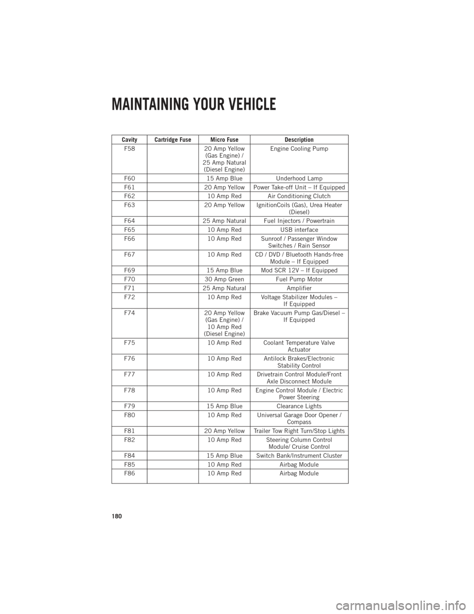
Cavity Cartridge Fuse Micro FuseDescription
F58 20 Amp Yellow
(Gas Engine) /
25 Amp Natural (Diesel Engine) Engine Cooling Pump
F60 15 Amp BlueUnderhood Lamp
F61 20 Amp Yellow Power Take-off Unit – If Equipped
F62 10 Amp Red Air Conditioning Clutch
F63 20 Amp Yellow IgnitionCoils (Gas), Urea Heater
(Diesel)
F64 25 Amp Natural Fuel Injectors / Powertrain
F65 10 Amp RedUSB interface
F66 10 Amp Red Sunroof / Passenger Window
Switches / Rain Sensor
F67 10 Amp Red CD / DVD / Bluetooth Hands-free
Module – If Equipped
F69 15 Amp Blue Mod SCR 12V – If Equipped
F70 30 Amp GreenFuel Pump Motor
F71 25 Amp Natural Amplifier
F72 10 Amp Red Voltage Stabilizer Modules –
If Equipped
F74 20 Amp Yellow
(Gas Engine) / 10 Amp Red
(Diesel Engine) Brake Vacuum Pump Gas/Diesel –
If Equipped
F75 10 Amp Red Coolant Temperature Valve
Actuator
F76 10 Amp Red Antilock Brakes/Electronic
Stability Control
F77 10 Amp Red Drivetrain Control Module/Front
Axle Disconnect Module
F78 10 Amp Red Engine Control Module / Electric
Power Steering
F79 15 Amp BlueClearance Lights
F80 10 Amp Red Universal Garage Door Opener /
Compass
F81 20 Amp Yellow Trailer Tow Right Turn/Stop Lights
F82 10 Amp Red Steering Column Control
Module/ Cruise Control
F84 15 Amp Blue Switch Bank/Instrument Cluster
F85 10 Amp RedAirbag Module
F86 10 Amp RedAirbag Module
MAINTAINING YOUR VEHICLE
180
Page 183 of 196

Cavity Cartridge Fuse Micro FuseDescription
F87 10 Amp Red Air Suspension / Trailer Tow /
Steering Column Control Module
F88 15 Amp Blue Instrument Panel Cluster
F90/F91 20 Amp Yellow Power Outlet (Rear seats)
Customer Selectable
F93 20 Amp YellowCigar Lighter
F94 10 Amp Red Shifter / Transfer Case Module
F95 10 Amp Red Rear Camera / Park Assist
F96 10 Amp Red Rear Seat Heater Switch
F97 25 Amp Natural Rear Heated Seats & Heated
Steering Wheel – If Equipped
F98 25 Amp Natural Front Heated Seats – If Equipped
F99 10 Amp RedClimate Control
F101 15 Amp Blue Electrochromatic Mirror / Smart
High Beams – If Equipped
F104 20 Amp Yellow Power Outlets (Instrument Panel/
Center Console)
CAUTION!
•When installing the power distribution center cover, it is important to ensure the
cover is properly positioned and fully latched. Failure to do so may allow water to
get into the power distribution center and possibly result in an electrical system
failure.
•When replacing a blown fuse, it is important to use only a fuse having the correct
amperage rating. The use of a fuse with a rating other than indicated may result
in a dangerous electrical system overload. If a properly rated fuse continues to
blow, it indicates a problem in the circuit that must be corrected.
MAINTAINING YOUR VEHICLE
181