Page 179 of 402

WARNING
In freezing temperatures the washer so-
lution may freeze on the rear window
glass and obscure your vision. Warm the
rear window with the defroster before
you wash the rear window.
CAUTION
Do not operate the washer continu- ously for more than 30 seconds.
Do not operate the washer if the reser- voir tank is empty.
Do not fill the window washer reservoir tank with washer fluid concentrates at
full strength. Some methyl alcohol
based washer fluid concentrates may
permanently stain the grille if spilled
while filling the window washer reser-
voir tank.
Pre-mix washer fluid concentrates with water to the manufacturer’s rec-
ommended levels before pouring the
fluid into the window washer reservoir
tank. Do not use the window washer
reservoir tank to mix the washer fluid
concentrate and water. If the rear window wiper operation is inter-
rupted by snow etc., the wiper may stop
moving to protect its motor. If this occurs,
turn the wiper switch to the OFF position
and remove the snow etc. on and around
the wiper arms. After about 1 minute, turn
the switch ON again to operate the wiper.
The rear window wiper and washer operate when
the power switch is in the ON position.
Turn the switch clockwise from the OFF position
to operate the wiper.
�1Intermittent (INT) — intermittent operation
(not adjustable)
�2Low (ON) — continuous low speed operation
Push the switch forward
�3to operate the
washer. Then the wiper will also operate several
times.
REAR WINDOW WIPER AND
WASHER SWITCH
2-40Instruments and controls
Page 188 of 402
To open the charge port lid, push the charge port
lid switch. See “Charge Port Lid” in the “Pre-
Driving Checks and Adjustments” section.To lock or unlock the charge connector, push the
charge connector lock switch. See “Charge
Connector Lock Switch” in the “Charging” sec-
tion.To turn off the charge timer, push the charge
timer OFF switch. See “Charging Timer” in the
“Charging” section.
CHARGE PORT LID SWITCH
CHARGE CONNECTOR LOCK SWITCH CHARGE TIMER OFF SWITCH
Instruments and controls2-49
Page 191 of 402

GLOVE BOX
WARNING
Keep the glove box lid closed while driv-
ing to prevent injury in case of an acci-
dent or a sudden stop.
To open the glove box, pull the handle.
To close, push the lid in until the lock latches.
CONSOLE BOX
To open the console box, push up the knob�A
and pull up the lid. To close, push the lid down
until it is latched.
CARGO COVER (IF SO EQUIPPED)
WARNING
Never put anything on the cargo cover, no matter how small. Any object on it
could cause an injury in an accident or
sudden stop. Do not leave the cargo cover in the
vehicle with it disengaged from the
holder.
Properly secure all cargo with ropes or straps to help prevent it from sliding or
shifting. Do not place cargo higher
than the seatbacks. In a sudden stop
or collision, unsecured cargo could
cause personal injury.
Your child could be seriously injured or killed in a collision if the child restraint
top tether strap is damaged.
–
If the cargo cover contacts the top
tether strap when it is attached to the
top tether anchor, remove the cargo
cover from the vehicle or secure it on
the cargo floor below its attachment
location. If the cargo cover is not re-
moved, it may damage the top tether
strap during a collision.
–Do not allow cargo to contact the top
tether strap when it is attached to the
top tether anchor. Properly secure the
cargo so it does not contact the top
tether strap. Cargo that is not properly
secured or that contacts the top tether
strap may damage the top tether strap
during a collision.
The cargo cover keeps the luggage compartment
contents hidden from the outside.
2-52Instruments and controls
Page 193 of 402
 to the hook. Doing so may cause
the hook to break.
The hook is located at the side of the luggage
room. Use the hook to sec")
LUGGAGE SIDE HOOK
CAUTION
Do not apply a total load of more than 4 lb
(2 kg) to the hook. Doing so may cause
the hook to break.
The hook is located at the side of the luggage
room. Use the hook to secure the Electric Vehicle
Supply Equipment (EVSE) .
POWER WINDOWS
WARNING
Make sure that all passengers have their hands, etc. inside the vehicle
while it is in motion and before closing
the windows. Use the window lock
switch to prevent unexpected use of
the power windows.
Do not leave children unattended in- side the vehicle. They could unknow-
ingly activate switches or controls and
become trapped in the window. Unat-
tended children could become in-
volved in serious accidents.
The power windows operate when the power
switch is in the ON position, or for about 45
seconds after the power switch is placed in the
OFF position. If the driver’s or front passenger’s
door is opened during this period of about 45
seconds, power to the windows is canceled.
Main power window switch (driver’s
side)
1. Driver side window
2. Front passenger side window
3. Rear left passenger side window
4. Rear right passenger side window
5. Window lock button
To open or close the window, push down
�Aor
pull up
�Bthe switch and hold it. The main switch
(driver’s side switches) will open or close all the
windows.
WINDOWS
2-54Instruments and controls
Page 194 of 402
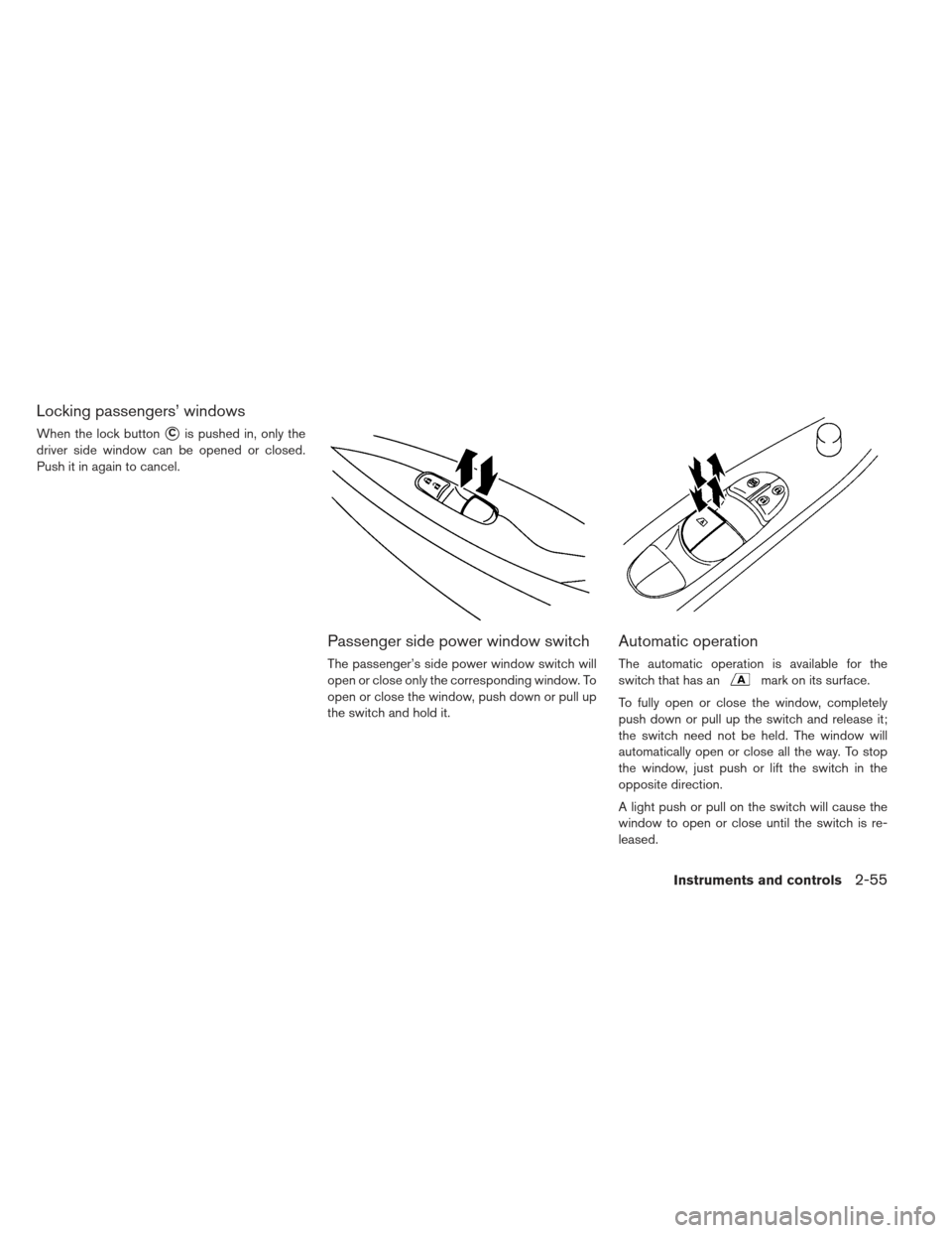
Locking passengers’ windows
When the lock button�Cis pushed in, only the
driver side window can be opened or closed.
Push it in again to cancel.
Passenger side power window switch
The passenger’s side power window switch will
open or close only the corresponding window. To
open or close the window, push down or pull up
the switch and hold it.
Automatic operation
The automatic operation is available for the
switch that has an
mark on its surface.
To fully open or close the window, completely
push down or pull up the switch and release it;
the switch need not be held. The window will
automatically open or close all the way. To stop
the window, just push or lift the switch in the
opposite direction.
A light push or pull on the switch will cause the
window to open or close until the switch is re-
leased.
Instruments and controls2-55
Page 196 of 402

MAP LIGHTS
Push the button to turn the map lights on. To turn
them off, press the button again.CEILING LIGHT
The ceiling light switch has three positions: ON ,
DOOR and OFF.
ON position
When the switch is in the ON position�1, the
ceiling light will illuminate.
DOOR position
When the switch is in the DOOR position�2, the
ceiling light will illuminate under the following
conditions:
the power switch is placed in the LOCK position.
– remains on for about 15 seconds. doors are unlocked by pushing the UNLOCK
button or the request switch, with the
power switch in the LOCK position – remains on for about 15 seconds.
any door is opened and then closed with the power switch in the LOCK position – remains on for about 15 seconds.
any door is opened with the power switch in the ACC or ON position – remains on while the door is opened. When the door is closed, the light turns off.
The light will automatically turn off after 10
minutes when the light remains illuminated
to prevent the battery from becoming dis-
charged.
OFF position
When the switch is in the OFF position�3, the
ceiling light will not illuminate, regardless of the
condition.
Instruments and controls2-57
Page 197 of 402

The HomeLink® Universal Transceiver provides
a convenient way to consolidate the functions of
up to three individual hand-held transmitters into
one built-in device.
HomeLink® Universal Transceiver:
Will operate most Radio Frequency (RF) de-vices such as garage doors, gates, home and
office lighting, entry door locks and security
systems.
Is powered by the vehicle’s 12-volt battery. No separate batteries are required. If the vehicle’s
12-volt battery is discharged or is discon-
nected, HomeLink® will retain all programming.
Once the HomeLink® Universal Trans-
ceiver is programmed, retain the original
transmitter for future programming proce-
dures (for example, new vehicle pur-
chases) . Upon sale of the vehicle, the pro-
grammed HomeLink® Universal
Transceiver buttons should be erased for
security purposes. For additional informa-
tion, see “Programming HomeLink®” later
in this section.
WARNING
Do not use the HomeLink® Universal Transceiver with any garage door
opener that lacks safety stop and re-
verse features as required by federal
safety standards. (These standards be-
came effective for opener models
manufactured after April 1, 1982.) A
garage door opener that cannot detect
an object in the path of a closing ga-
rage door and then automatically stop
and reverse, does not meet current
federal safety standards. Using a ga-
rage door opener without these fea-
tures increases the risk of serious in-
jury or death.
During the programming procedure, your garage door or security gate will
open or close (if the transmitter is
within range) . Make sure that people
or objects are clear of the garage door,
gate, etc. that you are programming.
Place the power switch in the ACC or ON position while programming the
HomeLink® Universal Transceiver.
PROGRAMMING HOMELINK®
If you have any questions or are having difficulty
programming your HomeLink® buttons, refer to
the HomeLink® web site at: www.homelink.com
or call 1-800-355-3515.
NOTE:
Place the ignition switch in the ACC posi-
tion when programming HomeLink®. It is
also recommended that a new battery be
placed in the hand-held transmitter of the
device being programmed to HomeLink®
for quicker programming and accurate
transmission of the radio-frequency.
1. Position the end of your hand-held transmitter
1–3 inches (2–8 cm) away from the
HomeLink® surface, keeping the HomeLink®
indicator light
�1in view.
HOMELINK® UNIVERSAL
TRANSCEIVER (IF SO EQUIPPED)
2-58Instruments and controls
Page 202 of 402

3 Pre-driving checks and adjustments
Keys...............................3-2
NISSAN Intelligent Keys® ...............3-2
Doors ............................. .3-3
Locking with Mechanical key ..............3-4
Locking with inside lock knob ..............3-4
Locking with power door lock switch ..........3-5
Automatic door locks .................. .3-5
Child safety rear door lock ................3-6
NISSAN Intelligent Key® system ..............3-6
NISSAN Intelligent Key® operating range of
the door lock/unlock function ..............3-8
Door locks/unlocks precaution .............3-8
NISSAN Intelligent Key® operation ..........3-9
12-volt battery saver system ..............3-10
Warning signals .................... .3-11
Troubleshooting guide ................ .3-12How to use remote keyless entry function
......3-13
Hood ............................ .3-16
Rear hatch ......................... .3-17
Secondary rear hatch release .............3-18
Charge port lid ....................... .3-18
Opening charge port lid ................3-18
Charge port cap .................... .3-19
Tilt steering column .................... .3-20
Tilt operation ...................... .3-20
Sun visors ......................... .3-21
Card holder (driver’s side only) ..............3-21
Mirrors ........................... .3-22
Inside rearview mirror ................. .3-22
Outside mirrors .................... .3-23
Vanity mirror ...................... .3-24