Page 401 of 602

N00731700260
In normal conditions, use the system in the AUTO mode and
follow these procedures:1. Set the blower speed s")
5-32 Comfort controls
5
Operating the air conditioning system (automatic
mode)
N00731700260
In normal conditions, use the system in the AUTO mode and
follow these procedures:1. Set the blower speed selection dial to the “AUTO” posi- tion.
2. Select the temperature control dial to the desired tempera- ture. The temperature can be set within a range of around
61 to 89. The temperature will increase as the dial is
turned to the right.
3. Set the mode selection dial to the “AUTO” position.
The vents (except between “ ” and “ ”), recirculation/out-
side air, blower speed, and ON/OFF of air conditioning will be
controlled automatically.
NOTE� Set the temperature at about 75 under normal conditions.
� While the engine coolant temperature is low, the tempera-
ture of the air from the heater will be cool/cold until the
engine warms up, even if you have selected warm air with
the dial. To prevent the windshield and windows from
fogging up, the vent mode will be changed to “ ” or
“ ” and the blower speed will be reduced.
BK0150700US.book 32 ページ 2012年3月22日 木曜日 午後6時46分
Page 406 of 602

Comfort controls5-37
5
NOTE�While the engine coolant temperature is low, the tempera-
ture of the air from the heater will be cool/cold until the
engine warms up, even if you have selected warm air with
the dial.
� When the temperature is set to the highest or the lowest
setting under the AUTO operation, the air selection and
the air conditioning will be automatically changed as fol-
lows.
Also, if the air selection is operated manually after an
automatic changeover, manual operation will be selected.
• Quick Heating (When the temperature is set to the high-
est setting)
Outside air will be introduced and the air conditioning
will stop.
• Quick Cooling (When the temperature is set to the low- est setting)
Inside air will be recirculated and the air conditioning
will operate.
The above indicates the factory settings. You can personalize
the air selection switch and air conditioning switch to match
your personal preferences.
Contact your Mitsubishi Motors dealer or a repair facility of
your choice for assistance.
Refer to “Personalizing the air conditioning switch (Changing
the function setting)” on page5-41.
Refer to “Personalizing the air selection (Changing the func-
tion setting)” on page5-39.
Mode selection dial
N00737100136
To change the amount of air flowing from the vents, turn the
mode selection dial. Refer to “Changing the mode selection”
on page 5-3.
BK0150700US.book 37 ページ 2012年3月22日 木曜日 午後6時46分
Page 411 of 602

N00731700286
In normal conditions, use the system in the AUTO mode and
follow these procedures:1. Set the blower speed s")
5-42 Comfort controls
5
Operating the air conditioning system (automatic
mode)
N00731700286
In normal conditions, use the system in the AUTO mode and
follow these procedures:1. Set the blower speed selection dial to the “AUTO” posi- tion.
2. Select the temperature control dial to the desired tempera- ture. The temperature can be set within a range of around
18 to 32. The temperature will increase as the dial is
turned to the right.
3. Set the mode selection dial to the “AUTO” position.
The vents (except “ ”), recirculation/outside air, blower
speed, and ON/OFF of air conditioning will be controlled auto-
matically.
NOTE� Set the temperature at about 25 under normal conditions.
� While the engine coolant temperature is low, the tempera-
ture of the air from the heater will be cool/cold until the
engine warms up, even if you have selected warm air with
the dial. To prevent the windshield and windows from
fogging up, the vent mode will be changed to “ ” or
“ ” and the blower speed will be reduced.
BK0150700US.book 42 ページ 2012年3月22日 木曜日 午後6時46分
Page 470 of 602

Comfort controls5-101
5
�In the following circumstances, moisture can form on
compact discs and inside the audio system, preventing
normal operation.
• When there is high humidity (for example, when it is raining).
• When the temperature suddenly rises, such as right after the heater is turned on in cold weather.
In this case, wait until the moisture has had time to dry
out.
� When the CD player is subjected to violent vibrations,
such as during off-road driving, the tracking may not
work.
� When storing compact discs, always store them in their
separate cases. Never place compact discs in direct sun-
light, or in any place where the temperature or humidity is
high.
� Never touch the flat surface of the disc where there isn’t a
label. This will damage the disc surface and could affect
the sound quality. When handling a compact disc, always
hold it by the outer edge and the center hole.
� To clean a disc, use a soft, clean, dry cloth. Wipe directly
from the center hole toward the outer edge. Do not wipe in
a circle. Never use any chemicals such as benzine, paint
thinner, a disc spray cleaner, or an anti-static agent on the
disc.
� Do not use a ball point pen, felt pen, pencil, etc. to write
on the label surface of the disc. �
Do not put additional labels or stickers on compact discs.
Also, do not use any compact disc on which a label or
sticker has started to peel off or any compact disc that has
stickiness or other contamination left by a peeled-off label
or sticker. If you use such a compact disc, the CD player
may stop working properly and you may not be able to
eject the compact disc.
BK0150700US.book 101 ページ 2012年3月22日 木曜日 午後6時46分
Page 478 of 602
 or a manual transaxle in “N”
(Ne")
For emergencies6-3
6
3. You could be injured if the vehicles move. Set the parkingbrake firmly on each vehicle. Put an automatic transaxle
or CVT in “P” (PARK) or a manual transaxle in “N”
(Neutral).
4. Turn the ignition switch to the “OFF” position or put the operation mode in OFF.NOTE� Turn off all lights, heater, and other electrical loads. This
will avoid sparks and help save both batteries.
5. Make sure your battery electrolyte is at the proper level. (Refer to “Battery” on page 7-21.) 6. Connect one end of one jumper cable to the positive (+)
terminal of the discharged battery (A), and the other end
to the positive (+) terminal of the booster battery (B).
WARNING
!� Perform step 4 on both vehicles beforehand. Make
sure that the cables or your clothes cannot be caught
by the fan or drive belt. Personal injury could result.
WARNING
!�If the electrolyte fluid is not visible, or looks frozen,
DO NOT ATTEMPT JUMP STARTING!!
The battery might split open or explode if the tem-
perature is below the freezing point or if it is not
filled to the proper level.
BK0150700US.book 3 ページ 2012年3月22日 木曜日 午後6時46分
Page 543 of 602
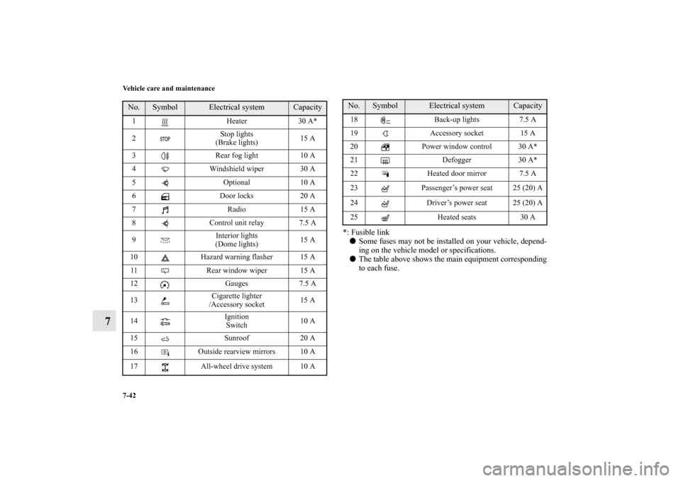
7-42 Vehicle care and maintenance
7
*: Fusible link� Some fuses may not be installed on your vehicle, depend-
ing on the vehicle model or specifications.
� The table above shows the main equipment corresponding
to each fuse.
No.
Symbol
Electrical system
Capacity
1 Heater30 A*
2 Stop lights
(Brake lights) 15 A
3 Rear fog light 10 A
4 Windshield wiper 30 A
5 Optional10 A
6 Door locks20 A
7 Radio15 A
8 Control unit relay 7.5 A
9 Interior lights
(Dome lights) 15 A
10 Hazard warning flasher 15 A
11 Rear window wiper 15 A
12 Gauges7.5 A
13 Cigarette lighter
/Accessory socket 15 A
14 Ignition
Switch 10 A
15 Sunroof20 A
16 Outside rearview mirrors 10 A
17 All-wheel drive system 10 A
18 Back-up lights 7.5 A
19 Accessory socket 15 A
20 Power window control 30 A*
21 Defogger30 A*
22 Heated door mirror 7.5 A
23 Passenger’s power seat 25 (20) A
24 Driver’s power seat 25 (20) A
25 Heated seats30 ANo.
Symbol
Electrical system
Capacity
BK0150700US.book 42 ページ 2012年3月22日 木曜日 午後6時46分
Page 545 of 602

7-44 Vehicle care and maintenance
7
*: Fusible link� Some fuses may not be installed on your vehicle, depend-
ing on the vehicle model or specifications.
� The table above shows the main equipment corresponding
to each fuse.
There are no 7.5 A, 25 A or 30 A spare fuses. If a fuse of one of
these capacities blows, replace it temporarily by borrowing one
of the fuses indicated below.
7.5 A: 10 A spare fuse
25 A: 20 A spare fuse
30 A: 30 A audio amplifier fuse
Replace the borrowed fuse with a fuse that has the correct
capacity as soon as possible.
17 Headlight
(low beam) (right) Discharge 20 A
18 Headlight
(low beam) (left) Halogen 10 A
19 Headlight
(low beam) (right) Halogen 10 A
20 ENG/POWER 10 A
21 Ignition coil 10 A
22 ENG/POWER 20 A
Fuel line heater 25 A
23 Fuel pump 15 A
24 Starter 30 A*
25 — — —
26 Anti-lock braking system 40 A*
27 Anti-lock braking system 30 A*
28 Air conditioning condenser fan
motor 30 A*
29 Radiator fan 40 A*
30 IOD IOD 30 A
31 Audio amplifier 30 ANo.
Symbol
Electrical system
Capacity
32 Diesel30 A
33 — Spare fuse10 A
34 — Spare fuse15 A
35 — Spare fuse20 ANo.
Symbol
Electrical system
Capacity
BK0150700US.book 44 ページ 2012年3月22日 木曜日 午後6時46分