2013 MITSUBISHI iMiEV battery
[x] Cancel search: batteryPage 64 of 258

NOTE
l The
indication lamp (3) comes on each time
a switch is pressed.
l If the UNLOCK switch (2) is pressed and
any of the doors or the tailgate is not opened
within approximately 30 seconds, relocking
will automatically occur.
l It is possible to modify functions as follows:
For further information, please contact your
MITSUBISHI MOTORS Authorized Service
Point.
• The time for automatic relocking can bechanged.
• The confirmation function (flashing of the turn-signal lamps) can be set to oper-
ate only when the doors and the tailgate
are locked or only when the doors and
the tailgate are unlocked.
• The confirmation function (this indicates locking or unlocking of the doors and the
tailgate with the flash of the turn-signal
lamps) can be deactivated.
• The number of times the turn-signal lamps are flashed by the confirmation
function can be changed.
l The keyless entry system does not operate in
the following conditions:
• The key is left in the key cylinder.
• The door or the tailgate is open.
l The remote control switch will operate with-
in approximately 4 m from the vehicle. How-
ever, the operating range of the remote con-
trol switch may change if the vehicle is loca-
ted near a power station, or radio/TV broad-
casting station.
l If either of the following problems occurs,
the battery may be exhausted. • The remote control switch is operated at
the correct distance from the vehicle, but
the doors and the tailgate are not locked/
unlocked in response.
• The indication lamp (3) is dim or does not come on.
For further information, please contact
your MITSUBISHI MOTORS Author-
ized Service Point.
If you replace the battery yourself, refer
to “Procedure for replacing the remote
control switch battery” on page 2-04.
l If your remote control switch is lost or dam-
aged, please contact your MITSUBISHI
MOTORS Authorized Service Point for a re-
placement remote control switch.
l If you wish to add a remote control switch,
we recommend you to contact a
MITSUBISHI MOTORS Authorized Service
Point.
A maximum of 4 remote control switches are
available for your vehicle.
Operation of the outside rear-view mir-
rors E00310800119
To fold
Within
30 seconds of locking the doors and the tail-
gate using the LOCK switch (1), press the LOCK
switch twice rapidly to fold the outside rear-view
mirrors.
To extend
Within 30 seconds of unlocking the doors and the
tailgate using the UNLOCK switch (2), press the
UNLOCK switch twice rapidly to return the out-
side rear-view mirrors to their extended positions. Procedure for replacing the remote
control switch battery
E00309500204
1. Before
replacing the battery, remove static
electricity from your body by touching a met-
al part such as doorknob of the room.
2. Remove the screw (A) from the remote con- trol switch. 3. With
the MITSUBISHI mark facing you, in-
sert the clothcovered tip of a straight blade
(or minus) screwdriver into the notch in the
remote control switch case and use it to open
the case. Locking and unlocking
2-04
2
OHAE13E1
Page 65 of 258

NOTE
l Be
sure to perform the procedure with the
MITSUBISHI mark facing you. If the
MITSUBISHI mark is not facing you when
you open the remote control switch case, the
switches may come out.
4. Remove the remote control transmitter from the remote control switch case. Then, open
the remote control transmitter using the meth-
od described in step 3. 5. Remove the old battery. 6. Install a new battery with the + side (B) down.
Coin type battery
CR1616
- side
+ side 7. Close the remote control transmitter firmly.
8.
Place the remote control transmitter in the re-mote control switch case, then securely close
the remote control switch case.
9. Attach the screw (A) removed in step 2.
10. Check the keyless entry system to see that it works.
NOTE l You may purchase a replacement battery at
an electric appliance store.
l A MITSUBISHI MOTORS Authorized Serv-
ice Point can replace the battery for you if
you prefer. CAUTION
l
When
the remote control switch case is
opened, be careful to keep water, dust,
etc. out. Also, do not touch the internal
components. Doors
E00300402187 CAUTION
l
Make
sure the doors are closed: driving
with doors not completely closed is dan-
gerous.
l Never leave children in the vehicle unat-
tended.
l Be careful not to lock the doors while the
key is inside the vehicle.
NOTE l To
prevent the key from being locked inside
the vehicle, neither the lock knob on the driv-
er’s door nor the key can be used to lock the
driver’s door when it is open.
To lock or unlock with the key 1- Lock
2-
Unlock Locking and unlocking
2-05 2
OHAE13E1
Page 69 of 258

Electric window control
E00302200550
The electric windows can only be operated with the
electric motor switch in the “ON” position. WARNING
l Before operating the electric window con-
trol, make sure that nothing can get trap-
ped (head, hand, finger, etc.).
l Never leave the vehicle without removing
the key.
l Never leave a child (or other person who
might not be capable of safe operation of
the electric window control) in the vehicle
alone.
l The child may tamper with the switch at
the risk of its hands or head being trap-
ped in the window.
Electric window control switch E00302301705
Each window opens or closes while the correspond-
ing switch is operated.
Driver’s switch (LHD)
Driver’s switch (RHD) 1- Driver’s door window
2-
Front passenger’s door window
3- Rear left door window
4- Rear right door window
5- Lock switch
Driver’s switches
The driver’s switches can be used to operate all
door windows.
A window can be opened or closed by operating
the corresponding switch.
Press the switch down to open the window, and
pull up the switch to close it.
If the switch for the driver’s door window is fully
pressed down, the door window automatically
opens completely.
If you want to stop the door window movement,
pull up the switch.
Passenger’s switches
The passenger’s switches can be used to operate
the corresponding passenger’s door windows. Press the switch down for opening the door win-
dow, and pull up the switch for closing.
NOTE
l Repeated
operation with the electric motor
unit stopped will run down the battery. Oper-
ate the window switches only while the elec-
tric motor unit is running.
Lock switch E00303101188
When this switch is operated, the passenger’s
switches
cannot be used to open or close the win-
dows and the driver’s switch cannot open or close
any windows other than the driver’s window. Locking and unlocking
2-09 2
OHAE13E1
Page 74 of 258

To recline the seatback
E00400601008
In
order to recline the seatback, lean forward slight-
ly, pull the seatback lock lever up, and then lean
backward to the desired position and release the lev-
er. The seatback will lock in that position. CAUTION
l
The
reclining mechanism of the seatback
is spring loaded, causing it to return to
the vertical position when the lock lever
is operated. When using the lever, sit
close to the seatback or hold it with your
hand to control its return motion. To adjust seat height (driver’s seat on-
ly)
E00400701054
To
adjust the seat height, operate the lever repeated-
ly. 1- Raise
2-
Lower Heated seats
E00401101097
The
heated seat can be operated with the electric
motor switch in the “ON” position. Operate the
switch as indicated by arrows. The heated seat
switch (A) is for the driver’s seat and the switch
(B) is for the passenger’s seat. The indication lamp
(C) will illuminate while the heater is on. 1- Heater on.
2-
Heater off. CAUTION
l
Switch off seat heaters when not in use.
l Continuous
use while the ready indicator
is not illuminated can cause the auxiliary
battery to run down.
l If the following types of persons use the
heated seats, they might become too hot Seat and seat belts
3-04
3
OHAE13E1
Page 104 of 258

l
If there is no operation for about 10 seconds
when the meter illumination control or serv-
ice reminder is shown, the display returns to
the odometer.
Odometer E00530800016
The odometer indicates the total distance the vehi-
cle has travelled.
NOTE
l Even
if the electric motor switch is turned to
“ACC” or “LOCK”, the odometer will be dis-
played for about 30 seconds after the reset but-
ton is pressed.
Tripmeter E00530900017
The tripmeter indicates the distance travelled dur-
ing a particular trip or period.
There
are two tripmeter displays: Tripmeter and .
Tripmeter can be used to measure the distance
travelled
since the current trip began. At the same
time, Tripmeter can be used to measure the dis-
tance from an intermediate location.
NOTE
l Even
if the electric motor switch is turned to
the “ACC” or “LOCK” position, the tripme-
ter will be displayed for about 30 seconds af-
ter the reset button is pressed.
To reset the tripmeter
To return the display to “0”, press the reset button
(A) for more than 2 seconds. Only the currently dis-
played value will be reset. NOTE
l If
the auxiliary battery terminal is removed,
the memories for the tripmeter and
displays are erased and the displays return to
0.
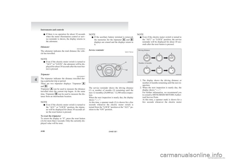
Service reminder E00517700164 The service reminder shows the driving distance
(1)
or number of months (2) remaining until the
next 12-monthly (20,000 km / 12,500 miles) inspec-
tion.
When the next inspection is nearly due, the display
shows “-----”.
At this time, a spanner mark (3) is shown for a few
seconds whenever the electric motor switch is
turned from the “LOCK” position or the “ACC” po-
sition to the “ON” position. NOTE
l Even
if the electric motor switch is turned to
the “ACC” or “LOCK” position, the service
reminder will be displayed for about 30 sec-
onds after the reset button is pressed.
Driving distance
Number of months 1. The
display shows the driving distance or
number of months remaining until the next in-
spection.
2. When the next inspection is nearly due, the display shows “-----”.
For further information, we recommend you
to consult a MITSUBISHI MOTORS Author-
ized Service Point.
At this time, a spanner mark is shown for a
few seconds whenever the electric motor Instruments and controls
4-04
4
OHAE13E1
Page 106 of 258

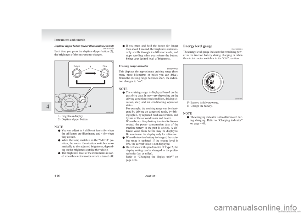
Daytime dipper button (meter illumination control)
E00529700028
Each
time you press the daytime dipper button (2),
the brightness of the instruments changes.
Bright Dim1- Brightness display
2-
Daytime dipper button
NOTE l You can adjust to 4 different levels for when
the tail lamps are illuminated and 4 for when
they are not.
l When the lamp switch is in the “AUTO” po-
sition, the meter illumination switches auto-
matically to the adjusted brightness, depend-
ing on the brightness outside the vehicle.
l The brightness level of the instruments is stor-
ed when the electric motor switch is turned off. l
If
you press and hold the button for longer
than about 1 second, the brightness automati-
cally scrolls through its different levels, and
stops scrolling when you release the button.
Select your desired level of brightness.
Cruising range indicator E00529900020
This displays the approximate cruising range (how
many
more kilometres or miles you can drive).
When the cruising range becomes short, the indica-
tion changes to “---”.
NOTE
l The cruising range is displayed based on the
past drive data. It may vary depending on the
driving condition (road condition, driving sit-
uation, etc.) and air conditioning operation
status.
For example, the cruising range can be short-
ened by driving on congested roads, by driv-
ing uphill, by repeated hard acceleration, and
by use of the air conditioner and heater.
When the auxiliary battery terminal is discon-
nected, the power consumption data of the
traction battery in the past is deleted. A dif-
ferent value from before may be displayed.
Be sure to use the display only for reference.
l When the traction battery is charged, the cruis-
ing range is updated. If the charge level is
low, the correct value is not displayed.
l On vehicles with speedometer of Type 2, the
display setting can be changed to the prefer-
red units (km or miles).
Refer to “Changing the display unit*” on
page 4-02. Energy level gauge
E00530000018
The
energy level gauge indicates the remaining pow-
er in the traction battery during charging or when
the electric motor switch is in the “ON” position. F- Battery is fully powered.
E- Charge the battery.
NOTE l The
charging indicator is also illuminated dur-
ing charging. Refer to “Charging indicator”
on page 4-09. Instruments and controls
4-06
4
OHAE13E1
Page 107 of 258

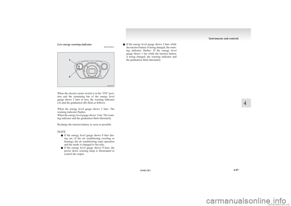
Low energy warning indicator
E00530300011When the electric motor switch is in the “ON” posi-
tion
and the remaining bar of the energy level
gauge shows 2 bars or less, the warning indicator
(A) and the graduation (B) flash as follows:
When the energy level gauge shows 2 bars: The
warning indicator flashes.
When the energy level gauge shows 1 bar: The warn-
ing indicator and the graduation flash alternately.
Recharge the traction battery as soon as possible.
NOTE
l If the energy level gauge shows 0 bars dur-
ing use of the air conditioning (cooling or
heating), the air conditioning stops operation
and the mode is changed to fan only.
l If the energy level gauge shows 0 bars, the
power down warning lamp is illuminated to
control the output. l
If
the energy level gauge shows 2 bars while
the traction battery is being charged, the warn-
ing indicator flashes. If the energy level
gauge shows 1 bar while the traction battery
is being charged, the warning indicator and
the graduation flash alternately. Instruments and controls
4-07 4
OHAE13E1
Page 108 of 258

Indication and warning lamps
E00501502220Type 1Type 21-
Low energy warning indicator
® p. 4-07
2. Selector lever position indicator ® p. 5-10
3- High-beam indication lamp ® p. 4-09
4- Turn-signal indication lamps/Hazard warning indication lamps ® p. 4-09
5- Position lamp indication lamp ® p. 4-09
6- Front fog lamp indication lamp* ® p. 4-09
7- Service reminder ® p. 4-04
8- Driver’s and front passenger’s seat belt warning lamp ® p. 3-09
9- Supplement Restraint System (SRS) warning lamp ® p. 3-29
10- Rear fog lamp indication lamp ® p. 4-09
11- Ready indicator ® p. 4-09 12-
Auxiliary battery charge warning lamp ® p. 4-10
13- Electric power steering system (EPS) warning lamp ® p. 5-17
14- Electric motor unit warning lamp ® p. 4-10
15- Brake warning lamp ® p. 4-09
16- Anti-lock brake system (ABS) warning lamp ® p. 5-15
17- Power down warning lamp ® p. 4-11
18- Active stability control (ASC) indication lamp ® p. 5-19
19- Active stability control (ASC) OFF indication lamp ® p. 5-19
20- Charging indicator ® p. 4-09
21- Door ajar warning lamp ® p. 4-10
22- Rear passenger’s seat belt warning lamps* ® p. 3-10Instruments and controls
4-08 4
OHAE13E1