2013 MITSUBISHI iMiEV warning
[x] Cancel search: warningPage 145 of 258

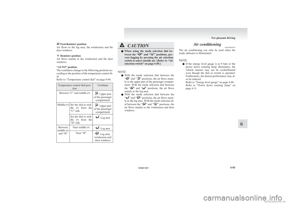
Foot/demister position
Air flows to the leg area, the windscreen and the
door windows. Demister position
Air
flows mainly to the windscreen and the door
windows.
“AUTO” position
The ventilators change to the following positions ac-
cording to the position of the temperature control di-
al.
Refer to “Temperature control dial” on page 6-04. Temperature control dial posi-
tion Ventilator
Between “C” and middle (•) : Upper part
of the passenger compartment
Middle (•) Set the dial to mid- dle
(•) from the
“C” side : Upper part
of the passenger compartment
Set the dial to mid-
dle
(•) from the
“H” side : Leg area
Between
middle (•) and “H” Near middle (•) : Leg area
Near “H” : Leg area,
windscreen and door windows CAUTION
l
When
using the mode selection dial be-
tween the “ ” and “ ” positions, pre-
vent fogging by pressing the air selection
switch to select outside air. (Refer to “Air
selection switch” on page 6-05.)
NOTE l With
the mode selection dial between the
“ ”
and “ ” positions, the air flows main-
ly to the upper part of the passenger compart-
ment. With the mode selection dial between
the “ ”
and “ ” positions, the air flows
mainly to the leg area.
l With the mode selection dial between the
“ ”
and “ ” positions, the air flows main-
ly to the leg area. With the mode selection di-
al between the “ ”
and “ ” positions, the
air flows mainly to the windscreen and door
windows. Air conditioning
E00700500478
The
air conditioning can only be used when the
ready indicator is illuminated.
NOTE
l If the energy level gauge is at 0 bars or the
power down warning lamp illuminates, the
vehicle interior may not be cooled/heated
even though the dial or switch is operated.
Furthermore, the demist performance may al-
so be reduced.
Refer to “Energy level gauge” on page 4-06.
Refer to “Power down warning lamp” on
page 4-11. For pleasant driving
6-03 6
OHAE13E1
Page 172 of 258

l
The unit may not successfully play back a
CD-R/RW that was made by the combina-
tion of writing software, a CD recorder
(CD-R/RW drive) and a disc if they are in-
compatible with one another.
l This player cannot play the CD-R/RW discs
if the session is not closed.
l This player cannot play CD-R/RW discs
which contain other than CD-DA or MP3 da-
ta (Video CD, etc.).
l Be sure to observe the handling instructions
for the CD-R/RW disc. WARNING
l Operating
the CD player in a manner oth-
er than specifically instructed herein may
result in hazardous radiation exposure.
Do not remove the cover and attempt to
repair the CD player by yourself. There
are no user serviceable parts inside. In
case of malfunction, we recommend you
to have it checked. Antenna
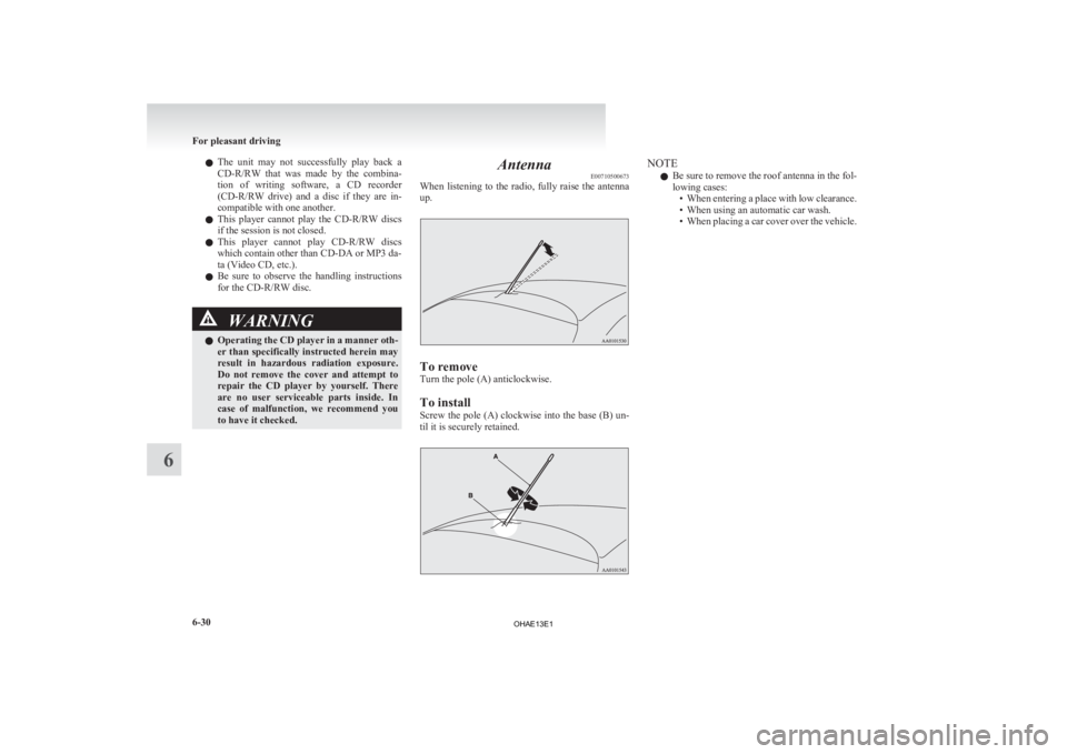
E00710500673
When
listening to the radio, fully raise the antenna
up. To remove
Turn the pole (A) anticlockwise.
To install
Screw
the pole (A) clockwise into the base (B) un-
til it is securely retained. NOTE
l Be
sure to remove the roof antenna in the fol-
lowing cases: • When entering a place with low clearance.
• When using an automatic car wash.
• When placing a car cover over the vehicle. For pleasant driving
6-30
6
OHAE13E1
Page 176 of 258

WARNING
l Place the USB memory device and the
USB connector cable so as not to inter-
fere with driving.
NOTE l Do
not connect the USB memory device to
the USB input terminal directly.
The USB memory device may be damaged.
5. To remove the USB connector cable, turn the electric motor switch to the “LOCK” posi-
tion first and perform the installation steps in
reverse.
How to connect an iPod E00762100258
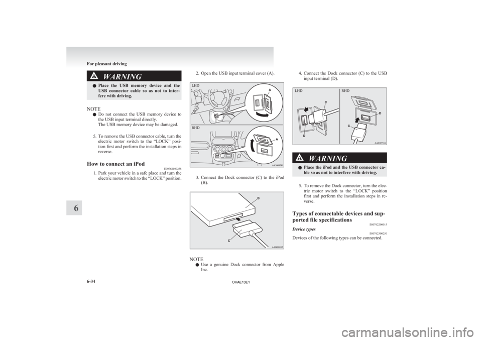
1. Park
your vehicle in a safe place and turn the
electric motor switch to the “LOCK” position. 2. Open the USB input terminal cover (A). 3. Connect the Dock connector (C) to the iPod
(B). NOTE
l Use
a genuine Dock connector from Apple
Inc. 4. Connect
the Dock connector (C) to the USB
input terminal (D). WARNING
l Place
the iPod and the USB connector ca-
ble so as not to interfere with driving.
5. To remove the Dock connector, turn the elec- tric
motor switch to the “LOCK” position
first and perform the installation steps in re-
verse.
Types of connectable devices and sup-
ported file specifications E00762200015
Device types E00762300250
Devices of the following types can be connected. For pleasant driving
6-34
6
OHAE13E1
Page 186 of 258

If the vehicle breaks down
E00800101355
If
the vehicle breaks down on the road, move it to
the shoulder and use the hazard warning flashers and/
or the warning triangle etc.
Refer to “Hazard warning flasher switch” on page
4-15. WARNING
l If
you are not able to safely assess the ve-
hicle due to vehicle damage, do not touch
the vehicle. Leave the vehicle and contact
a MITSUBISHI MOTORS Authorized
Service Point or another specialist and
convey that this is an electric vehicle first.
If the ready indicator goes out while
driving
Vehicle
operation and control are affected if the
ready indicator goes out while driving. Before mov-
ing the vehicle to a safe area, be aware of the fol-
lowing:
l The brake booster may become inoperative
and the pedal effort will increase. Press
down the brake pedal harder than usual.
l The power steering system may not operate,
the steering wheel feels heavy when turning it. Emergency starting
E00800502819
If
the electric motor unit cannot be started because
the auxiliary battery is weak or dead, the battery
from another vehicle can be used with jumper ca-
bles to start the electric motor unit. WARNING
l To
start the electric motor unit by using
jumper cables from another vehicle, per-
form the correct procedures according to
the instruction below. Incorrect proce-
dures could result in a fire or explosion
or damage to the vehicles. CAUTION
l
The
electric motor unit cannot be started
by pulling or pushing the vehicle.
l Always wear protective eye goggles when
working near the battery.
l Keep the battery out of the reach of chil-
dren.
l Do not attempt jump start the auxiliary
battery while the traction battery is being
charged.
Doing so could damage the charging
equipment or the vehicle.
1. Get
the vehicles close enough so the jumper cables can reach, but be sure the vehicles
aren’t touching each other. CAUTION
l
Check
the other vehicle. It must have a 12-
volt battery.
If the other system isn’t 12-volt, shorting
can damage both vehicles.
2. Turn
off all lamps, heater and other electrical loads.
3. Set the parking brake firmly on your vehicle and move the selector lever into the “P” posi-
tion.
4. Set the parking brake firmly on another vehi- cle. Put an A/T in “P” (PARK) or a M/T in
“N” (Neutral).
5. Turn the ignition switch or the electric motor switch to the “LOCK” position. WARNING
l Perform
step 5 on both vehicles before-
hand.
Make sure that the cables or your clothes
cannot be caught by the fan or drive belt.
Personal injury could result.
6. Remove
the battery cover, and then make sure auxiliary battery electrolyte is at the prop-
er level.
Refer to “Auxiliary battery” on page 8-12. For emergencies
7-02
7
OHAE13E1
Page 187 of 258

WARNING
l If electrolyte fluid is not visible, or ap-
pears to be frozen, Do Not Attempt Jump
Starting!
A battery might rupture or explode if the
temperature is below the freezing point
or if it is not filled to the proper level.
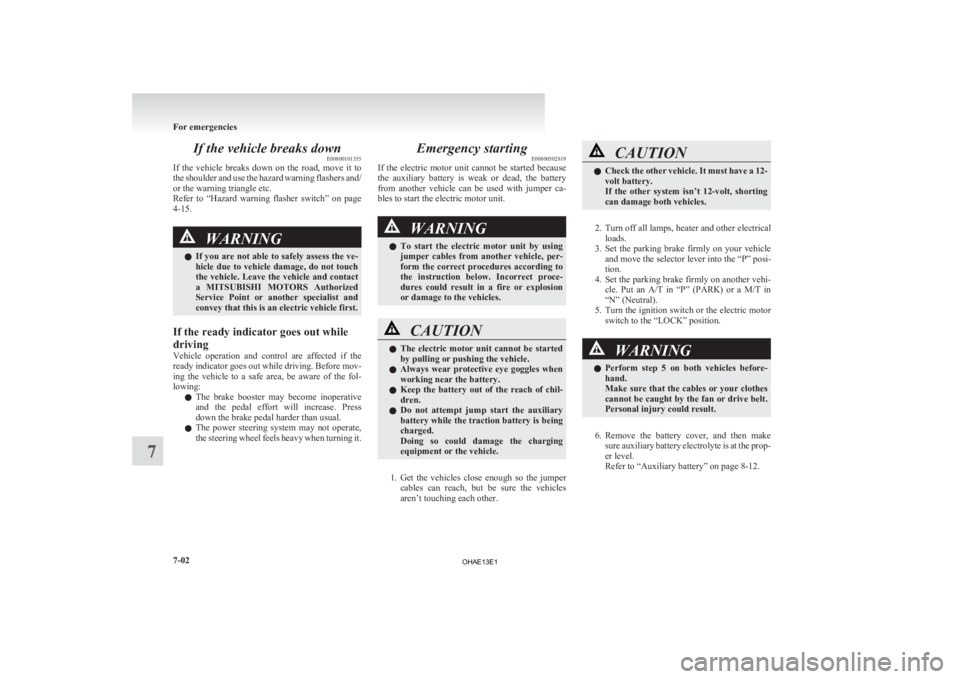
7. Connect
one end of one jumper cable to the positive (+) terminal of the discharged bat-
tery (A), and the other end to the positive (+)
terminal of the booster battery (B).
Connect one end of the other jumper cable to
the negative (-) terminal of the booster bat-
tery, and the other end to the designated loca-
tion of the vehicle with the discharged bat-
tery at the point farthest from the battery. WARNING
l Make
sure you observe the following or-
der when connecting the cables: → →
→
l
Make sure you make connection to the
correct
designated location (as shown in
the illustration). If the connection is made
directly to the negative (-) side of the dis-
charged battery, flammable gases gener-
ated from the battery might catch fire
and explode.
l When connecting the jumper cables, do
not connect the positive (+) cable to the
negative (-) terminal. Otherwise sparks
might cause explosion of the battery. CAUTION
l
Take
care not to get the jumper cable
caught in the cooling fan or other rotat-
ing part in the bonnet room or engine com-
partment.
l Use the proper cables suitable for the bat-
tery size to prevent overheating of the ca-
bles.
l Check the jumper cables for damage and
corrosion before use.
8. Start
the engine in the vehicle which has the booster battery, let the engine idle a few mi-
nutes, then start the electric motor unit in the
vehicle with the discharged battery.
9. Check that the ready indicator illuminates.
[When the ready indicator illuminates]
Stop
the engine of another vehicle, discon-
nect the cables in the reverse order and
charge the auxiliary battery for more than 30
minutes.
After the auxiliary battery is charged, contin-
ue the process from step 16.
[When the ready indicator does not illuminate]
Both the auxiliary battery and the traction bat-
tery have gone flat at the same time.
Charge the auxiliary battery and the traction
battery by the following procedures (from
steps 10 to 14).
10. Keep connecting the jumper cable to each ve- hicle, turn the electric motor switch of your
vehicle to the “LOCK” position.
NOTE l The jumper cable needs to be connected to
the auxiliary battery when you start charging
the traction battery because the on board
charger etc. operate with a power source of
auxiliary battery.
11. Charge the traction battery by regular charg- ing. (Refer to “Regular charging” on page
1-08.)
12. When the charging indicator on the instru- ment cluster is illuminated, stop the engine
of another vehicle, disconnect the cables in
the reverse order. For emergencies
7-03 7 LHD
RHD
OHAE13E1
Page 188 of 258

NOTE
l When
the regular charge connector is connec-
ted to the charge port, the charging indicator
is blinking. When charging is started, the
charging indicator is illuminated.
l The auxiliary battery is automatically charg-
ed while charging the traction battery.
13. Charge the traction battery for more than 1 hour.
14. Disconnect the charging cable. (Refer to “Regular charging” on page 1-08.)
15. Turn the electric motor switch to the “START” position, make sure that the ready
indicator on the instrument cluster is illumi-
nated.
If the ready indicator does not illuminate, per-
form the procedure again from step 7.
If charging cannot be performed, consult a
MITSUBISHI MOTORS Authorized Service
Point.
16. Refit the battery cover. (Refer to “Auxiliary battery” on page 8-12.) WARNING
l Do
not charge the auxiliary battery using
an external battery charger while the aux-
iliary battery is mounted in the vehicle.
Doing so could cause the auxiliary bat-
tery to catch fire and explode and could
result in damage to the vehicle.
l Keep sparks, cigarettes, and flames away
from the auxiliary battery because the bat-
tery may produce an explosion.
l Use adequate ventilation when charging
or using the auxiliary battery in an en-
closed space.
l Remove all the caps before charging the
auxiliary battery.
l Electrolyte is corrosive diluted sulphuric
acid.
If electrolyte (battery acid) comes into con-
tact with your hands, eyes, clothes and
the painted surface of your vehicle, it
should be thoroughly flushed with water.
If electrolyte gets in your eyes, flush them
with water immediately and thoroughly,
and get prompt medical attention.
NOTE l If
the electric motor unit is started without
fully charging the auxiliary battery, it might
cause the anti-lock brake warning lamp to il-
luminate. Refer to “Anti-lock brake system
(ABS)” on page 5-15. Tyre repair kit
E00800901311
This
kit enables emergency repair of a small punc-
ture in the tread area of a tyre that has run over a
nail, screw, or similar object.
Storage
The tyre repair kit is stowed under the rear seat cush-
ion. The storage location of the tyre repair kit
should be remembered in case of an emergency. 1- Tyre compressor
2-
Tyre repair set
3- Tyre sealant bottle
4- Filler hose
5- Extension hose (This hose is used for removal of sealant. It
is not used in emergency puncture repair.)
6- Valve insert (spare)
7- Valve remover
8- Speed restriction sticker For emergencies
7-04
7
OHAE13E1
Page 190 of 258

l
Use the tyre sealant only at ambient tempera-
tures of -30 °C to + 60 °C.
l Effect an emergency repair without pulling
out the object (nail, screw, etc.) that is stuck
in the tyre.
l Do not use the tyre sealant if the tyre has
been damaged by being driven when insuffi-
ciently inflated (e.g. bumps, cuts, cracks etc.
on the tyre).
l Wipe tyre sealant off the paintwork immedi-
ately with a damp cloth.
l Immediately wash clothes contaminated with
tyre sealant.
Before repairing a tyre, first stop your vehicle in a
safe, flat location. 1. Park the vehicle on level and stable ground.
2. Set the parking brake firmly.
3. Move the selector lever to the “P” (PARK)position and turn the electric motor switch to
the “LOCK” position.
4. Turn on the hazard warning flashers and set up a warning triangle, flashing signal lamp,
etc., at an adequate distance from the vehi-
cle, and have all your passengers leave the ve-
hicle.
5. Take out the tyre repair kit.
6. Shake the tyre sealant bottle well. NOTE
l In
cold conditions (when the ambient temper-
ature is 0 °C or lower), thickening of the tyre
sealant can make the tyre sealant hard to
squeeze out of the bottle. Warm the bottle in-
side the vehicle.
7. Take the cap (C) off the tyre sealant bottle (D). Do not remove the seal (E). Screw the
filler hose (D) onto the bottle (E). As you
screw the filler hose onto the bottle, the seal
will break, allowing the sealant to be used. CAUTION
l
If
you shake the bottle after screwing on
the hose, sealant may spray out of the hose.
8. Take the valve cap (G) off the tyre valve (H), then
press the valve remover (I) onto the
valve as illustrated. Allow all of the air in the
tyre to escape. 9. Remove
the valve insert (J) by turning it anti-
clockwise using the valve remover (I). Put
the removed valve insert in a clean place so
it does not get dirty. For emergencies
7-06
7
OHAE13E1
Page 194 of 258

CAUTION
l
Be sure to check the tyre pressure for con-
firmation that the emergency repair pro-
cedure is complete.
NOTE l Please
give the empty sealant bottle to your
MITSUBISHI MOTORS Authorized Service
Point when you purchase new sealant or dis-
pose of the sealant bottle according to nation-
al regulations for the disposal of chemical
waste.
l A tyre in which puncture sealant has been
used should ideally be replaced with a new
one. If you wish to have such a tyre properly
repaired for reuse, please contact a
MITSUBISHI MOTORS Authorized Service
Point or another specialist. Note that a proper
repair is impossible following an emergency
repair if the puncture hole cannot be located.
l The manufacturer is unable to guarantee that
all tyre punctures can be repaired with the
tyre repair kit, in particular cuts or perfora-
tions with a diameter of more than 4 mm or
away from the tyre’s tread. The manufacturer
is not liable for damage sustained through im-
proper use of the tyre repair kit.
l The manufacturer is not liable for damage sus-
tained through re-use of any tyre in which
tyre sealant has been used. Towing
E00801503754
If your vehicle needs to be towed
If
you need to tow your vehicle, we recommend
that you contact a MITSUBISHI MOTORS Author-
ized Service Point or a commercial tow truck service.
Transport the vehicle on a flatbed truck or tow the
vehicle either with all wheels or the rear wheels
(drive wheels) off the ground.
Flat bed type
Dolly type
Towing with rear wheels off the ground In the following cases, transport the vehicle with
all wheels on a carriage.
l The
ready indicator illuminates but the vehi-
cle does not move, or an abnormal noise is
produced.
l The electric motor unit warning lamp comes
on.
l Inspection of the vehicle’s underside reveals
that oil or some other fluid is leaking.
l Your vehicle body is severely damaged or de-
formed in the event of an accident. If a wheel gets stuck in a ditch, do not try to tow
the
vehicle. Please contact your MITSUBISHI
MOTORS Authorized Service Point or a commer-
cial tow truck service for assistance.
In an emergency your vehicle may be temporarily
towed with the rear wheels (drive wheels) on the
ground only when the traction battery is complete-
ly discharged.
If your vehicle is to be towed by another vehicle,
carefully tow your vehicle for the shortest distance
possible and in accordance with the instructions giv-
en in “Emergency towing” in this part.
The regulations concerning towing may differ from
country to country. It is recommended that you
obey the regulations of the area where you are driv-
ing your vehicle.
Towing the vehicle by a tow truck WARNING
l Never
get under your vehicle after it has
been lifted by a tow truck.
l Never ride in a vehicle that is being towed.
l Never tow the vehicle with rear wheels
(drive wheels) on the ground. This may
cause damage to the electric motor. This
may also cause a fire, if wiring in the elec-
tric motor unit room becomes damaged. For emergencies
7-10
7
OHAE13E1