2013 MERCEDES-BENZ B-CLASS SPORTS warning
[x] Cancel search: warningPage 243 of 336
X
Attach hook =to the cargo
compartment's uppers eal?.
X To close: detach hook =from seal ?.
X Fasten hook =to the bracket on the
underside of the cargo compartment floor.
X Fold the trunk floor down.
X Press the trun kfloor down until it engages.
Setting the height of the trunk floor The stowage well under the trunk floor can be
increased or decreased in size as necessary.
To do this, you can lock the floor at two
differen
theights. The upper catch gives a flat
load surface when the rear bench seat is
folded forward. X
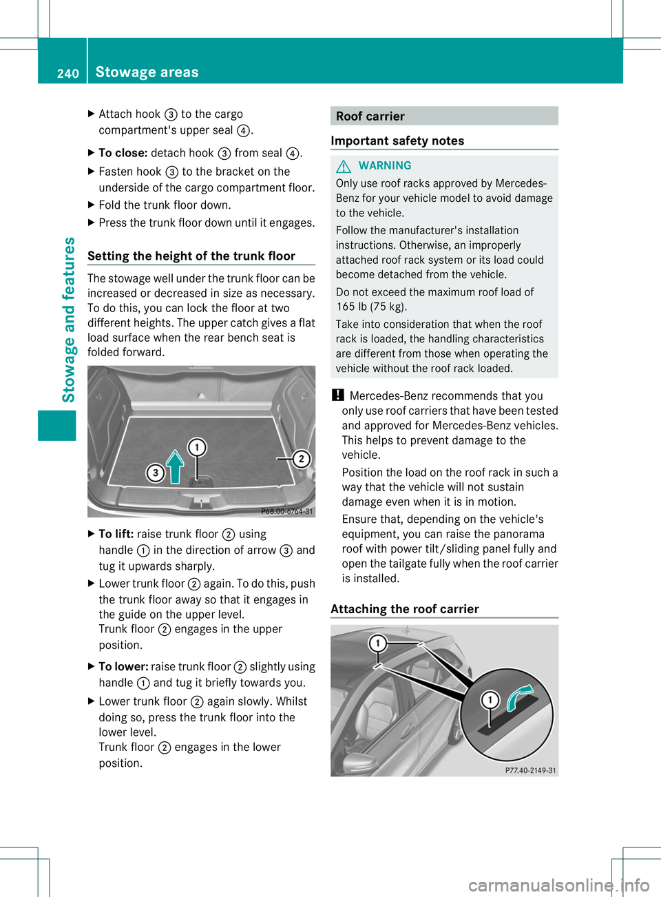
To lift: raise trunk floor ;using
handle :in the direction of arrow =and
tug it upwards sharply.
X Lower trunk floor ;again. To do this, push
the trun kfloor away so that it engages in
the guide on the upper level.
Trunk floor ;engages in the upper
position.
X To lower: raise trunk floor ;slightly using
handle :and tug it briefly towards you.
X Lower trunk floor ;again slowly. Whilst
doing so, press the trunk floor into the
lower level.
Trunk floor ;engages in the lower
position. Roof carrier
Important safety notes G
WARNING
Only use roof racks approved by Mercedes-
Ben zfor your vehicle model to avoid damage
to the vehicle.
Follow the manufacturer' sinstallation
instructions. Otherwise, an improperly
attached roo frack system or its load could
become detached from the vehicle.
Do not exceed the maximum roof load of
165 lb (75 kg).
Take into consideratio nthat when the roof
rack is loaded, the handling characteristics
are different from those when operating the
vehicle without the roof rack loaded.
! Mercedes-Benzr ecommends that you
only use roof carriers that have been tested
and approved for Mercedes-Benzv ehicles.
This helps to preven tdamage to the
vehicle.
Positio nthe load on the roof rack in such a
way that the vehicle will not sustain
damage even when it is in motion.
Ensure that, depending on the vehicle's
equipment, you can raise the panorama
roof with power tilt/sliding panel fully and
open the tailgate fully when the roof carrier
is installed.
Attaching the roof carrier 240
Stowage areasStowage and features
Page 244 of 336
X
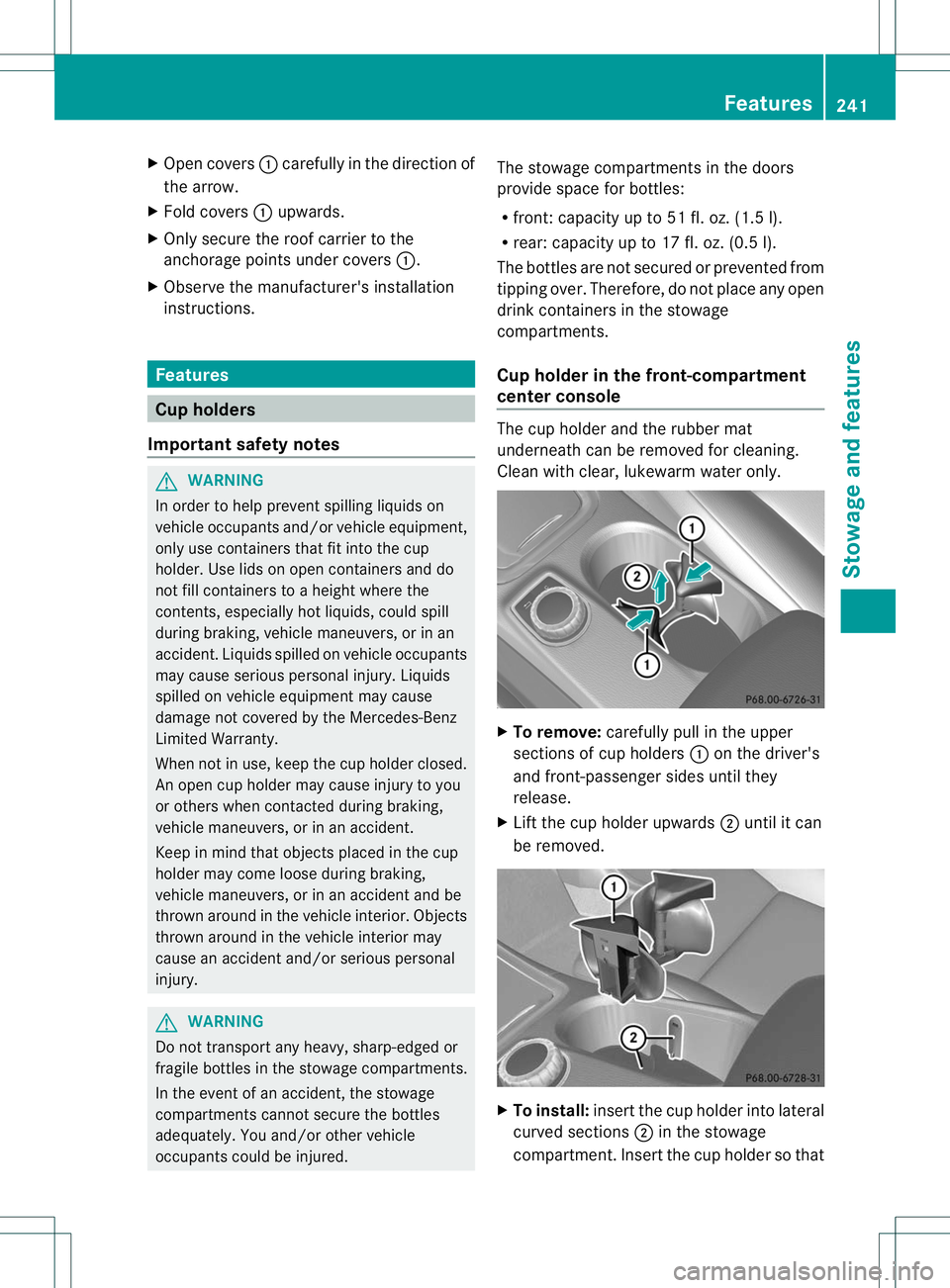
Open covers :carefully in the direction of
the arrow.
X Fold covers :upwards.
X Only secure the roof carrier to the
anchorage points under covers :.
X Observe the manufacturer's installation
instructions. Features
Cup holders
Important safety notes G
WARNING
In order to help prevent spilling liquids on
vehicle occupants and/or vehicle equipment,
only use containers that fit into the cup
holder. Use lids on open containers and do
not fill containers to aheight where the
contents, especially hot liquids, could spill
during braking, vehicle maneuvers, or in an
accident. Liquids spilled on vehicle occupants
may cause serious personal injury. Liquids
spilled on vehicle equipment may cause
damage not covered by the Mercedes-Benz
Limited Warranty.
When not in use, keep the cup holder closed.
An open cup holder may cause injury to you
or others when contacted during braking,
vehicle maneuvers, or in an accident.
Keep in mind that objects placed in the cup
holder may come loose during braking,
vehicle maneuvers, or in an accident and be
thrown around in the vehicle interior. Objects
thrown around in the vehicle interior may
cause an acciden tand/o rserious personal
injury. G
WARNING
Do not transport any heavy, sharp-edged or
fragile bottles in the stowage compartments.
In the event of an accident, the stowage
compartments cannot secure the bottles
adequately. You and/or other vehicle
occupants could be injured. The stowage compartments in the doors
provide space for bottles:
R
front: capacity up to 51 fl. oz. (1.5 l).
R rear: capacity up to 17 fl. oz. (0.5 l).
The bottles are not secured or prevented from
tipping over. Therefore, do not place any open
drink containers in the stowage
compartments.
Cup holder in the front-compartment
center console The cup holder and the rubber mat
underneath can be removed for cleaning.
Clean with clear, lukewarm water only.
X
To remove: carefully pull in the upper
sections of cup holders :on the driver's
and front-passenger sides until they
release.
X Lift the cup holder upwards ;until it can
be removed. X
To install: insert the cup holder into lateral
curved sections ;in the stowage
compartment .Inser tthe cup holder so that Features
241Stowage and features Z
Page 245 of 336
the wedge of the uppe
rsection of cup
holder :faces forwards.
X Press the cup holder downwards until it
engages on the right and left-hand sides.
Cup holder in the rear seat armrest !
Do not sit on or support your body weight
on the rear seat armrest when it is folded
down, as you could otherwise damage it.
! Close the cup holder before folding the
rear seat armrest up. Otherwise, the cup
holder could be damaged. X
Fold down the rear seat armrest.
X To open: press the fron tofcup holder :
or ;.
Cup holder :or; extends automatically.
X To close: slide the cup holder bac kuntil it
engages. Sun visors
Overview G
WARNING
Do not use the vanity mirror while driving.
Keep the vanity mirrors in the sun visors
closed while the vehicle is in motion.
Reflected glare can endanger you and others. :
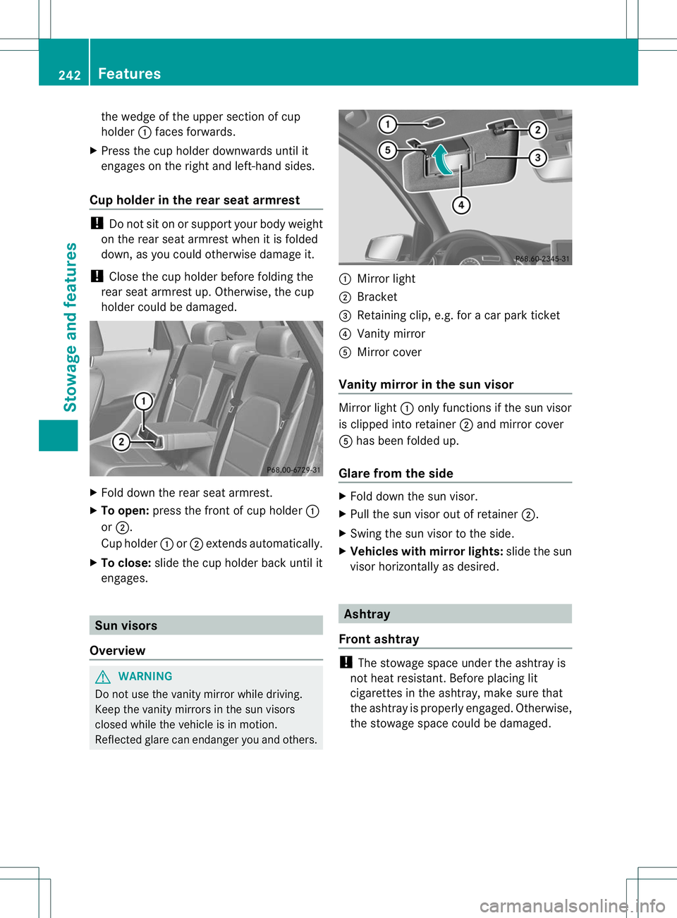
Mirro rlight
; Bracket
= Retaining clip, e.g. for a car park ticket
? Vanity mirror
A Mirror cover
Vanity mirror in the sun visor Mirror light
:only functions if the sun visor
is clipped into retainer ;and mirror cover
A has been folded up.
Glare from the side X
Fold down the sun visor.
X Pull the sun visor out of retainer ;.
X Swing the sun visor to the side.
X Vehicles with mirror lights: slide the sun
visor horizontally as desired. Ashtray
Front ashtray !
The stowage space under the ashtray is
not heat resistant. Before placing lit
cigarettes in the ashtray, make sure that
the ashtray is properly engaged. Otherwise,
the stowage space could be damaged. 242
FeaturesStowage and features
Page 246 of 336
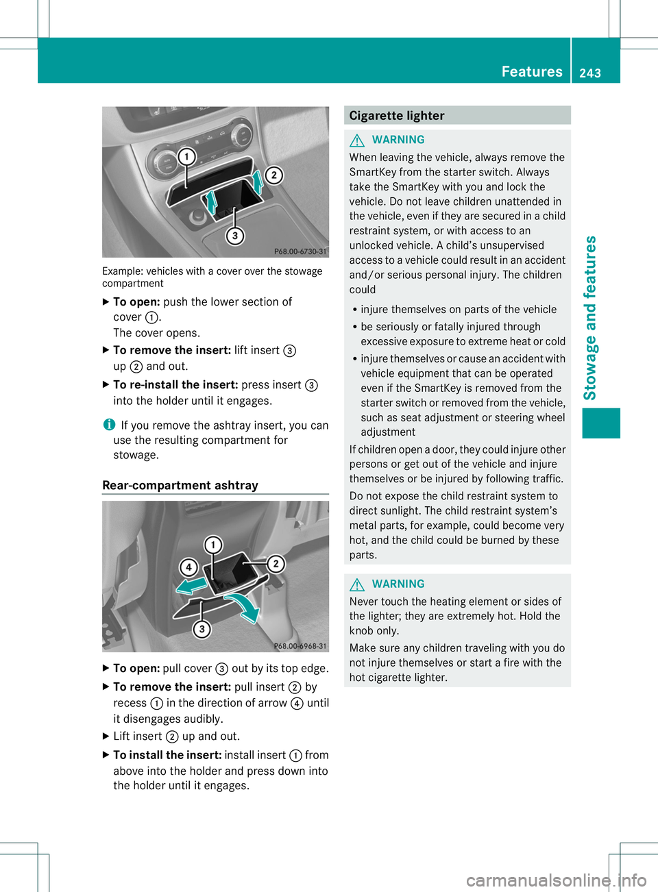
Example: vehicles with a cove
rover the stowage
compartment
X To open: push the lower section of
cover :.
The cover opens.
X To remove the insert: lift insert=
up ; and out.
X To re-install the insert: press insert=
into the holder until it engages.
i If you remove the ashtray insert, you can
use the resulting compartment for
stowage.
Rear-compartment ashtray X
To open: pull cover =out by its top edge.
X To remove the insert: pull insert;by
recess :in the directio nofarrow?until
it disengages audibly.
X Lift insert ;up and out.
X To install the insert: install insert:from
above into the holder and press downi nto
the holde runtil it engages. Cigarette lighter
G
WARNING
Whe nleaving the vehicle, always remove the
SmartKey from the starter switch. Always
take the SmartKey with you and lock the
vehicle. Do not leave children unattended in
the vehicle, even if they are secured in a child
restraint system, or with access to an
unlocked vehicle. Achild’s unsupervised
access to a vehicle could result in an accident
and/or serious personal injury. The children
could
R injure themselves on parts of the vehicle
R be seriously or fatally injured through
excessive exposure to extreme heat or cold
R injure themselves or cause an accident with
vehicle equipment that can be operated
even if the SmartKey is removed from the
starter switch or removed from the vehicle,
such as seat adjustment or steering wheel
adjustment
If children open a door, they could injure other
persons or get out of the vehicle and injure
themselves or be injured by following traffic.
Do not expose the child restraint system to
direct sunlight. The child restraint system’s
metal parts, for example, could become very
hot, and the child could be burned by these
parts. G
WARNING
Never touch the heating element or sides of
the lighter; they are extremely hot. Hold the
knob only.
Make sure any children traveling with you do
not injure themselves or start a fire with the
hot cigarette lighter. Features
243Stowage and features Z
Page 249 of 336
USA only: you can find information and a
description of all available features under
"Owners Online" at http://www.mbusa.com.
System self-test
After you have switched on the ignition, the
system carries out a self-diagnosis.
Am
alfunction in the system has been
detected if one of the following occurs:
R The indicator lamp in the SOSb utton does
not come on during the system self-test.
R The indicator lamp in the FRoadside
Assistance butto ndoes not light up during
self-diagnosis of the system.
R The indicator lamp in the ïMB Info call
button does not light up during self-
diagnosis of the system.
R The indicator lamp in one or more of the
following buttons continues to light up red
after the system self-diagnosis:
-the SOS button
- the F Roadside Assistance call
button
- the ï MB Info call button
R the mbrace Inoperative or
mbrace Service Not Activated message
appears in the multifunction display after
the system self-diagnosis.
If a malfunction is indicated as outlined
above, the system may not operate as
expected. In the event of an emergency,
assistance must be summoned by other
means.
Have the system checked at the nearest
authorized Mercedes-Benz Center or contact
the following service hotlines:
R USA: Mercedes-Benz Customer Assistance
Center at
1-800-FOR-MERCedes (1-800-367-6372)
or 1-888-990-9007
R Canada: Customer Service at
1-888-923-8367 Emergency call Important safety notes
G
WARNING
If the indicator lamp in the SOS button is
flashing continuously and no voice
connection with the Response center has
been established, then the mbrace system
has not been able to initiate an emergency call
(e.g. the relevant mobile phone network is not
available).
The Call Failed message is displayed in the
multifunction display and must be confirmed.
Should this occur, assistance must be
summoned by other means.
! Alicense agreement must exis tinorder
to activate the mbrace service. Ensure that
yours ystem is activated and ready fo ruse,
and press the ïMB Info call button to
register. If any of the steps mentioned is
not carried out, the system may not be
activated.
If you have questions aboutt he activation,
contact one of the following telephone
assistance services:
R USA: Mercedes-BenzC ustomer
Assistance Cente runder
1-800-FOR-MERCedes
(1-800-367-6372) or 1-888-990-9007
R Canada: Customer Service at
1-888-923-8367
An emergency call is dialed automatically if
an ai rbag or Emergency Tensioning Device is
triggered.
i You canno tend an automatically
triggered emergency call yourself.
An emergency call can also be initiated
manually.
As soo nas the emergency call has been
initiated, the indicator lamp in the SOS button
flashes. The Connecting Call message
appears on the multifunction display.
The audio output is muted. 246
FeaturesStowage and features
Page 250 of 336
Once the connection has been made, the
Call Connected
message appears in the
multifunction display.
All important information on the emergency
is transmitted, for example:
R Current location of the vehicle (as
determined by the GPS system)
R Vehicle identification number
R Information on the severity of the accident
Shortly after the emergency call has been
initiated, a voice connection is automatically
established between the Mercedes-Benz
Customer Assistance Center and the vehicle
occupants. If the vehicle occupants respond,
the Mercedes-Benz Customer Assistance
Center attempts to get more information on
the emergency.
i If there is no response from the vehicle
occupants, an ambulance is immediately
sent to the vehicle.
Making an emergency call G
WARNING
If you feel at any way in jeopardy when in the
vehicle (e.g. smoke or fire in the vehicle,
vehicle in a dangerous road location), please
do not wait for voice contact after you have
pressed the SOS button. Carefully leave the
vehicle and move to a safe location. The
Response Center will automatically contact
local emergency officials with the vehicle's
approximate location if they receive an
automatic SOS signal and cannot make voice
contact with the vehicle occupants. X
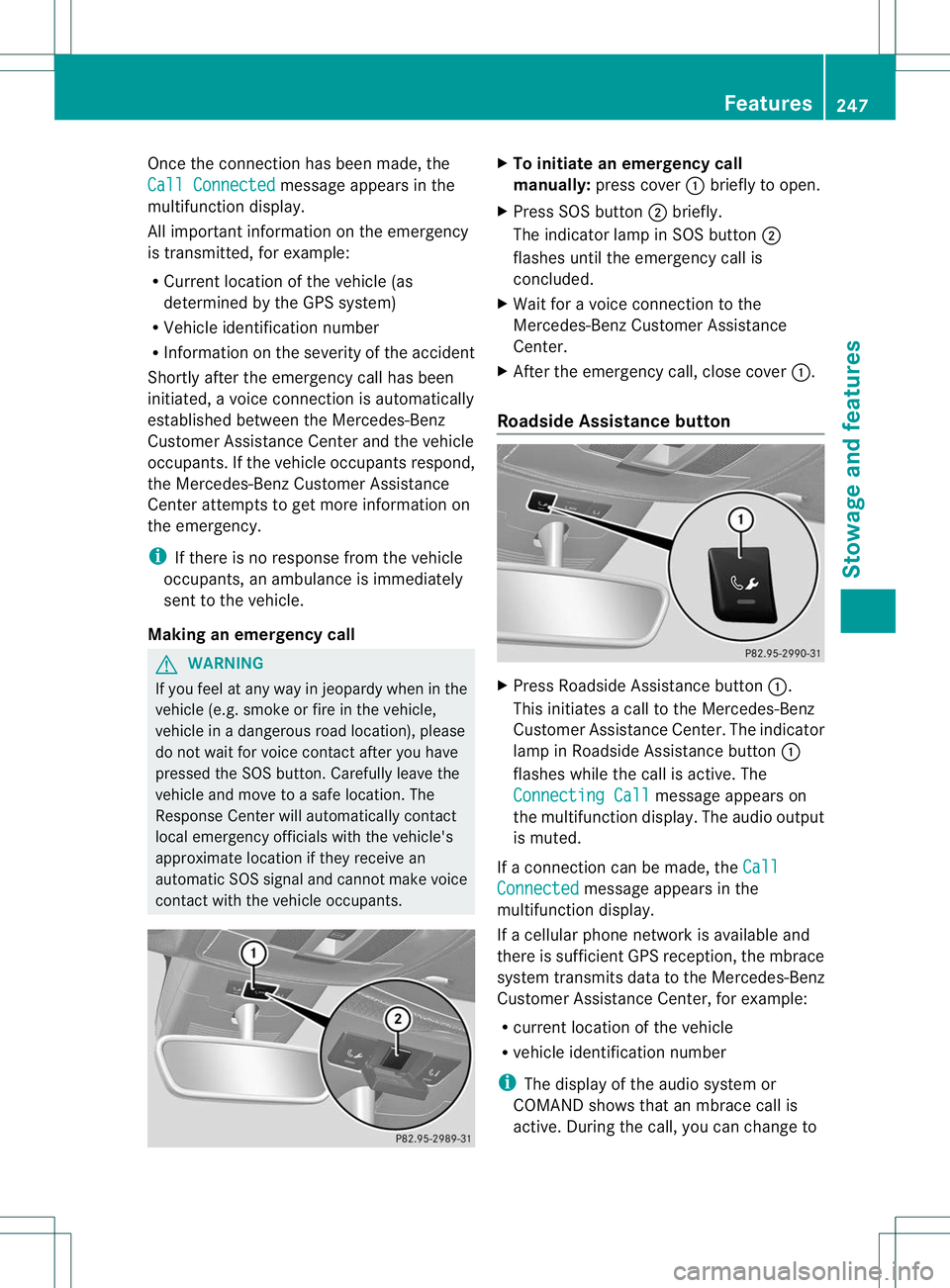
To initiate an emergency call
manually: press cover :briefly to open.
X Press SOS button ;briefly.
The indicator lamp in SOS button ;
flashes until the emergency call is
concluded.
X Wait for a voice connection to the
Mercedes-Benz Customer Assistance
Center.
X After the emergency call, close cover :.
Roadside Assistance button X
Press Roadside Assistance button :.
This initiates a call to the Mercedes-Benz
Customer Assistance Center. The indicator
lamp in Roadside Assistance button :
flashes while the call is active. The
Connecting Call message appears on
the multifunction display. The audio output
is muted.
If a connection can be made, the Call Connected message appears in the
multifunction display.
If a cellular phone network is available and
there is sufficient GPS reception, the mbrace
system transmits data to the Mercedes-Benz
Customer Assistance Center, for example:
R current location of the vehicle
R vehicle identification number
i The display of the audio system or
COMAND shows that an mbrace call is
active. During the call, you can change to Features
247Stowage and features Z
Page 256 of 336
X
To start route guidance: selectYes .
An overview of the route is shown in the
display.
i If you select No , the saved route can be
called up later in the navigation menu.
X Select Start .
Route guidance is started.
i Downloaded and saved data can be called
up again in COMAND. Further information
can be found in the "COMAND", "Online
and Internet services" and "Download
destination/route" sections.
Speed alert You can define the uppe
rspeed limit, which
must not be exceeded by the vehicle. If this
selected speed is exceeded by the vehicle, a
message will be sent to the Customer
Assistance center. The Customer Assistance
center then forwards this information to you.
You can select the way in which you receive
this information beforehand. Possible options
include SMS, E-Mail or an automated call.
The data which is sent to the Customer
Assistance center contains the following
information:
R the location where the speed limit was
exceeded
R the time at which the speed limit was
exceeded
R the selected speed limit which was
exceeded
Geo fencing Geo fencing allows you to select areas which
the vehicle should not enter or leave. You will
be informed if the vehicle crosses the
boundaries of the selected areas. You can
select the way in which you receive this
information beforehand. Possible options
include SMS, E-Mail or an automated call.
The area can be determined as either a circle
or a polygon with a maximum of ten corners.
You can specify up to ten areas simultaneously. Different settings are
possible for each area.
USA only: these settings can be called up
under "Owners Online" at http://
www.mbusa.com.
Alternatively, you can trigger an MB Info call
and inform the customer service
representative that you wish to activate geo
fencing.
Currently inactive areas can be activated by
SMS.
Triggering the vehicle alarm
With this function, you can trigger the
vehicle's panic alarm via SMS. An alarm
sounds and the exterior lighting flashes.
Depending on the setting, the panic alarm
lasts five or ten seconds. Afterwards, the
alarm switches off.
Garage door opener
Important safety notes G
WARNING
Before programming the integrated remote
control to a garage door opener or gate
operator, make sure people and objects are
out of the way of the device to prevent
potential harm or damage. When
programming a garage door opener, the door
moves up or down. When programming a gate
operator, the gate opens or closes.
Do not use the integrated remote control with
any garage door opener that lacks safety stop
and reverse features as required by U.S.
federal safety standards (this includes any
garage door opener model manufactured
before April 1, 1982). A garage door that
cannot detect an object - signaling the door
to stop and reverse - does not meet current
U.S .federal safety standards.
When programming a garage door opener,
park vehicle outside the garage. Features
253Stowage and features
Z
Page 257 of 336
Do not ru
nthe engine while programming the
integrated remote control. Inhalation of
exhaust gas is hazardous to your health. All
exhaust gas contains carbon monoxide (CO),
and inhaling it can cause unconsciousness
and possible death. All exhaust gas contains
carbon monoxide (CO), and inhaling it can
cause unconsciousness and possible death.
The HomeLink ®
garage door opener
integrated in the rear-view mirror allows you
to operate up to three different door and gate
systems.
i Certain garage door drives are
incompatible with the integrated garage
door opener. If you have difficulty
programming the integrated garage door
opener, contact an authorized Mercedes-
Benz Center.
Alternatively, you can call the following
telephone assistance services:
R USA: Mercedes-BenzC ustomer
Assistance Cente rat
1-800-FOR-MERCedes
R Canada: Customer Service at
1-800-387-0100
R HomeLink ®
hotline 1-800-355-3515
(free of charge)
More information on HomeLink ®
and/or
compatible products is also available
online at http://www.homelink.com.
i USA only:
This device complies with par t15oft he
FCC Rules. Operation is subject to the
following two conditions:
1. This device may not cause harmful
interference, and
2. this device must accept any interference
received, including interference that may
cause undesired operation.
Any unauthorized modification to this
device could void the user's authority to
operate the equipment.
FCC ID: CB2HMIHL4 i
Canada only:
This device complies with the RSS-210
Rules of Industry Canada.O peration is
subjec tto the following two conditions:
1. This device may not cause harmful
interference, and
2. this device must accept any interference
received, including interference that may
cause undesired operation of the device.
Any unauthorized modification to this
device could void the user's authority to
operate the equipment.
IC: 279B-HMIHL4
Programming Programming buttons
G
WARNING
Only press the button on the integrated
garage door opener if there are no persons or
objects present within the sweep of the
garage door. Persons could otherwise be
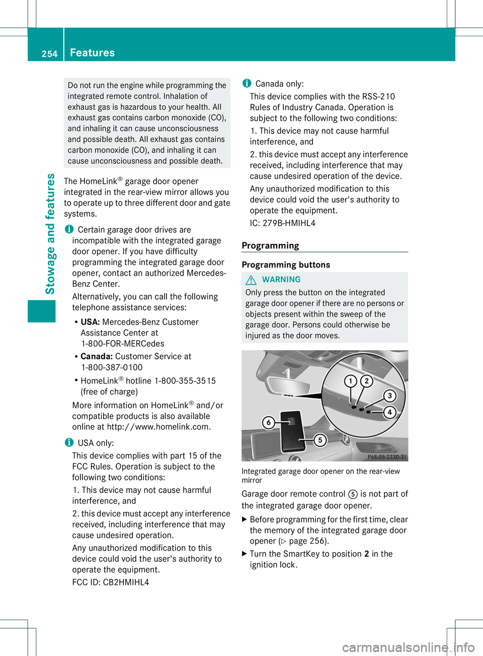
injured as the door moves. Integrated garage door opener on the rear-view
mirror
Garage door remote control
Ais not part of
the integrated garage door opener.
X Before programming for the first time, clear
the memory of the integrated garage door
opener (Y page 256).
X Turn the SmartKey to position 2in the
ignition lock. 254
FeaturesStowage and features