Page 65 of 116

Before You Begin Programming HomeLink®
•Ensure that your vehicle is parked outside of the garage before you begin program-
ming.
•For efficient programming and accurate transmission of the radio-frequency signal,
it is recommended that a new battery be placed in the hand-held transmitter of the
device that is being programmed to the HomeLink
®system.
• Erase all channels before you begin programming. To erase the channels, place the ignition switch into the ON/RUN position, then press and hold the two outside
HomeLink
®buttons (I and III) for up 20 seconds or until the red indicator flashes.
NOTE:
Erasing all channels should only be performed when programming HomeLink
®for
the first time. Do not erase channels when programming additional buttons.
•
If you have any problems, or require assistance, please call toll-free 1–800–355–3515
or, on the Internet at www.HomeLink.com for information or assistance.
Programming A Rolling Code
• For programming Garage Door Openers that were manufactured after 1995. These Garage Door Openers can be identified by the “LEARN” or “TRAIN” button
located where the hanging antenna is attached to the Garage Door Opener. It is
NOT the button that is normally used to open and close the door. The name and
color of the button may vary by manufacturer.
• Place the ignition switch into the ON/RUN position.
• Place the hand-held transmitter 1 to 3 in (3 to 8 cm) away from the HomeLink
®
button you wish to program while keeping the HomeLink®indicator light in view.
• Simultaneously press and hold both the HomeLink
®button you want to program
and the hand-held transmitter button.
• Continue to hold both buttons and observe the indicator light. The HomeLink
®
indicator will flash slowly and then rapidly after HomeLink®has received the
frequency signal from the hand-held transmitter. Release both buttons after the
indicator light changes from slow to rapid.
•
At the garage door opener motor (in the garage), locate the “LEARN” or “TRAINING”
button. This can usually be found where the hanging antenna wire is attached to the
garage door opener motor. Firmly press and release the “LEARN” or “TRAINING”
button.
NOTE:
You have 30 seconds in which to initiate the next step after the LEARN button has
been pressed.
• Return to the vehicle and press the programmed HomeLink
®button twice
(holding the button for two seconds each time). If the device is plugged in and
activates, programming is complete.
ELECTRONICS
63
Page 66 of 116
 to
complete the training.
• To program the remaining two HomeLink
®buttons, repeat each step for each
remainin")
NOTE:
If the device does not activate, press the button a third time (for two seconds) to
complete the training.
• To program the remaining two HomeLink
®buttons, repeat each step for each
remaining button. DO NOT erase the channels.
Programming A Non-Rolling Code
• For programming Garage Door Openers manufactured before 1995.
• Turn the ignition switch to the ON/RUN position.
• Place the hand-held transmitter 1 to 3 in (3 to 8 cm) away from the HomeLink
®
button you wish to program while keeping the HomeLink®indicator light in view.
• Simultaneously press and hold both the HomeLink
®button you want to program
and the hand-held transmitter button.
• Continue to hold both buttons and observe the indicator light. The HomeLink
®
indicator will flash slowly and then rapidly after HomeLink®has received the
frequency signal from the hand-held transmitter. Release both buttons after the
indicator light changes from slow to rapid.
•
Press and hold the programmed HomeLink®button and observe the indicator light.
NOTE:
• If the indicator light stays on constantly, programming is complete and thegarage door (or device) should activate when the HomeLink
®button is pressed.
• To program the two remaining HomeLink
®buttons, repeat each step for each
remaining button. DO NOT erase the channels.
Using HomeLink®
•To operate, press and release the programmed HomeLink®button. Activation will
now occur for the programmed device (i.e., garage door opener, gate operator, security
system, entry door lock, home/office lighting, etc.,). The hand-held transmitter of the
device may also be used at any time.
WARNING!
• Your motorized door or gate will open and close while you are programming the
universal transceiver. Do not program the transceiver if people or pets are in the
path of the door or gate.
• Do not run your vehicle in a closed garage or confined area while programming
the transceiver. Exhaust gas from your vehicle contains Carbon Monoxide (CO)
which is odorless and colorless. Carbon Monoxide is poisonous when inhaled
and can cause you and others to be severely injured or killed.
ELECTRONICS
64
Page 67 of 116

POWER INVERTER
• A 115 Volt, 150 Watt AC power in-verter is located on the front of the
center console.
• This outlet can power cellular phones, electronics and other low power de-
vices requiring power up to 150 Watts.
NOTE:
The power inverter is designed with
built-in overload protection. If the power
rating of 150 Watts is exceeded, the power
inverter will automatically shut down.
Once the electrical device has been removed from the outlet, the inverter should
automatically reset. If the power rating exceeds approximately 170 Watts, the power
inverter may have to be reset manually. To reset the inverter manually, unplug the
device and plug it in again. To avoid overloading the circuit, check the power ratings on
electrical devices prior to using the inverter.
WARNING!
• To Avoid Serious Injury or Death DO NOT: • use a three-prong adaptor
• insert any objects into the receptacles
• touch with wet hands
• Close the lid when not in use. If this outlet is mishandled, it may cause an electric shock and failure.
ELECTRONICS
65
Page 68 of 116
POWER OUTLET
• The power outlet is located on the instrument panel below the climate control andis powered when the ignition switch is in the ON/RUN position.
• The outlet can operate a conventional cigar lighter unit or power accessories designed for use with a standard power outlet adapter.
NOTE:
•
Do not exceed the maximum power of 160 Watts (13 Amps) at 12 Volts. If the 160 Watt
(13 Amp) power rating is exceeded, the fuse protecting the system will need to be
replaced.
• Power outlets are designed for accessory plugs only. Do not insert any other object in the power outlet as this will damage the outlet and blow the fuse. Improper use
of the power outlet can cause damage not covered by your new vehicle warranty.
ELECTRONICS
66
Page 69 of 116
FOUR-WHEEL DRIVE OPERATION
•This vehicle has two full time, on-demand, four-wheel-drive (4WD) systems avail-
able, Freedom Drive I and Freedom-Drive II. They provide for all-weather, all-terrain
capability for added driving security in less-than-ideal road conditions.
Freedom-Drive I™ Four Wheel Drive System
• The vehicle will constantly monitor wheel slippage and transfer power to the axle that can use it the most.
• For additional traction in sand, deep snow or loose traction surfaces, the “4WD Lock” sends equal amounts of the torque to the front and rear axles at low speeds.
OFF-ROAD CAPABILITIES
67
Page 70 of 116

• To activate, pull the T-handle, located in between the front driver and passengerseats, up once and release. The “4WD Indicator Light” will come on in the cluster.
• This can be done on the fly, at any vehicle speed. To deactivate, simply pull on the T-handle one more time. The “4WD Indicator Light” will then turn off.
Trail Rated
®Freedom-Drive II™Four Wheel Drive System (IF EQUIPPED) • This system offers all the benefits of Freedom Drive I™ plusthe rugged capability of true Trail-Rated off road performance
with three additional features:
• Off-Road Mode
• Pulling up on the T-handle while the gear shift lever is in the Low position activates the Off-Road mode.
• This feature allows power to be sent to all four wheels when additional traction is required while also delivering enhanced off-road capability for water fording,
moving on steep grades and rock crawling.
• Brake Lock Differential
• This feature helps keep the vehicle moving forward when one wheel loses traction by directing power from the wheel that slips to the wheel with more grip on the
same axle providing more traction in off-road situations.
• Hill Descent Control/Hill Start Assist
• The Hill Descent Control System maintains vehicle speed while descending hills during off-road driving situations and is available in both low and reverse gears.
• This allows a smooth and controlled hill descent on rough or slippery terrain without the driver needing to touch the brake pedal.
• The Hill Start Assist system assists the driver when starting a vehicle from a stop on a hill.
OFF-ROAD CAPABILITIES
68
Page 71 of 116

Engine/
Transmission Frontal Area Max. GTW
(Gross Trailer Wt.) Max. Tongue Wt.
(See Note)
2.0L Auto/Man 22 sq ft
(2.04 sq m) 1,000 lbs (450 kg)")
TRAILER TOWING WEIGHTS
(MAXIMUM TRAILER WEIGHT RATINGS)
Engine/
Transmission Frontal Area Max. GTW
(Gross Trailer Wt.) Max. Tongue Wt.
(See Note)
2.0L Auto/Man 22 sq ft
(2.04 sq m) 1,000 lbs (450 kg) 150 lbs (50 kg)
2.4L Auto/Man 22 sq ft
(2.04 sq m) 1,000 lbs (450 kg) 150 lbs (50 kg)
2.4L Auto With
Freedom Drive II Off Road
Package (AWL)32 sq ft
(3.0 sq m) 2,000 lbs (907 kg) 300 lbs (136 kg)
Refer to local laws for maximum trailer towing speeds.
NOTE:
The trailer tongue weight must be considered as part of the combined weight of
occupants and cargo, and should never exceed the weight referenced on the Tire and
Loading Information placard.
RECREATIONAL TOWING
(BEHIND MOTORHOME, ETC.)
Towing ConditionWheels OFF the Ground Manual Transmission Automatic
Transmission
Flat Tow None• Transmission in
NEUTRAL
• Key in ACC Position NOT ALLOWED
Dolly Tow Front
OK (FWD Only) OK (FWD Only)
Rear NOT ALLOWED NOT ALLOWED
On Trailer All
OK OK
NOTE:
Vehicles equipped withmanual transmissionsmay be recreationally towed (flat towed)
at any legal highway speed, for any distance, if themanual transmissionis in NEUTRAL
and the ignition key is in the ACC position.
CAUTION!
• Do not flat tow any vehicle equipped with a automatic transmission. Damage to the drivetrain will result. If these vehicles require towing, make sure all drive
wheels are off the ground.
•
Front or rear wheel lifts should not be used. Internal damage to the transmission
or transfer case will occur if a front or rear wheel lift is used when recreational
towing.
UTILITY
69
Page 72 of 116

ROADSIDE ASSISTANCE
•Dial toll-free 1-800-521-2779 for U.S. Residents or 1-800-363-4869 for Canadian
Residents.
• Provide your name, vehicle identification number, license plate number, and your location, including the telephone number from which you are calling.
• Briefly describe the nature of the problem and answer a few simple questions.
• You will be given the name of the service provider and an estimated time of arrival. If you feel you are in an “unsafe situation”, please let us know. With your consent,
we will contact local police or safety authorities.
INSTRUMENT CLUSTER WARNING LIGHTS
- Electronic Stability Control (ESC) Activation/Malfunction Indicator Light
• If the “ESC Activation/Malfunction Indicator Light” comes on continuously withthe engine running, a malfunction has been detected in the ESC system. If this
light remains on after several ignition cycles, and the vehicle has been driven
several miles (kilometers) at speeds greater than 30 mph (48 km/h), we recom-
mend you do not operate the vehicle. Have the vehicle serviced immediately.
• The “ESC Activation/Malfunction Indicator Light” starts to flash as soon as the tires lose traction and the ESC system becomes active. If the light begins to flash
during acceleration, ease up on the accelerator and apply as little throttle as
possible. Be sure to adapt your speed and driving to the prevailing road conditions.
The light also flashes when TCS is active. To improve the vehicle's traction when
starting off in deep snow, sand or gravel, it may be desirable to switch the ESC
system to Partial Off mode by momentarily pressing the ESC Off
switch.
- Tire Pressure Monitoring System (TPMS) Light
•Each tire, including the spare (if provided), should be checked monthly, when cold
and inflated to the inflation pressure recommended by the vehicle manufacturer on
the vehicle placard or tire inflation pressure label. (If your vehicle has tires of a
different size than the size indicated on the vehicle placard or tire inflation pressure
label, you should determine the proper tire inflation pressure for those tires.)
• As an added safety feature, your vehicle has been equipped with a Tire Pressure Monitoring System (TPMS) that illuminates a low tire pressure telltale when one
or more of your tires is significantly under-inflated. Accordingly, when the low tire
pressure telltale illuminates, you should stop and check your tires as soon as
possible, and inflate them to the proper pressure. Driving on a significantly
under-inflated tire causes the tire to overheat and can lead to tire failure.
Under-inflation also reduces fuel efficiency and tire tread life, and may affect the
vehicle’s handling and stopping ability.
WHAT TO DO IN EMERGENCIES
70
 1
1 2
2 3
3 4
4 5
5 6
6 7
7 8
8 9
9 10
10 11
11 12
12 13
13 14
14 15
15 16
16 17
17 18
18 19
19 20
20 21
21 22
22 23
23 24
24 25
25 26
26 27
27 28
28 29
29 30
30 31
31 32
32 33
33 34
34 35
35 36
36 37
37 38
38 39
39 40
40 41
41 42
42 43
43 44
44 45
45 46
46 47
47 48
48 49
49 50
50 51
51 52
52 53
53 54
54 55
55 56
56 57
57 58
58 59
59 60
60 61
61 62
62 63
63 64
64 65
65 66
66 67
67 68
68 69
69 70
70 71
71 72
72 73
73 74
74 75
75 76
76 77
77 78
78 79
79 80
80 81
81 82
82 83
83 84
84 85
85 86
86 87
87 88
88 89
89 90
90 91
91 92
92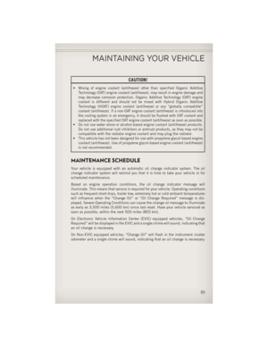 93
93 94
94 95
95 96
96 97
97 98
98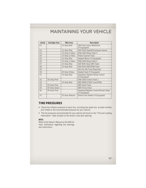 99
99 100
100 101
101 102
102 103
103 104
104 105
105 106
106 107
107 108
108 109
109 110
110 111
111 112
112 113
113 114
114 115
115
 systems avail-
able, Freedom Drive I and Freedom-Drive II. They provide for all-weather, all-terrain
cap")