Page 223 of 563

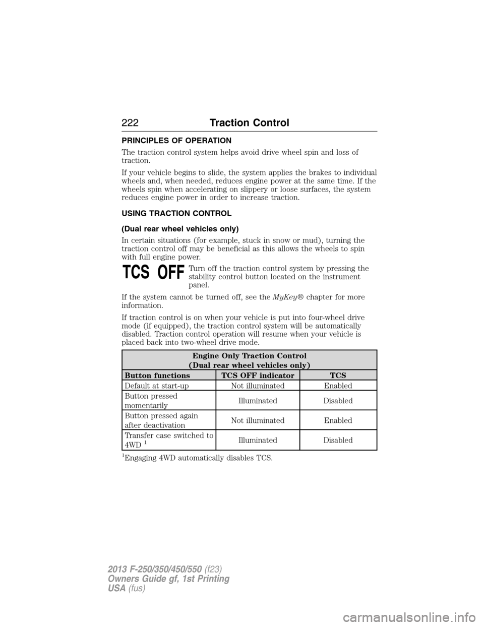
PRINCIPLES OF OPERATION
The traction control system helps avoid drive wheel spin and loss of
traction.
If your vehicle begins to slide, the system applies the brakes to individual
wheels and, when needed, reduces engine power at the same time. If the
wheels spin when accelerating on slippery or loose surfaces, the system
reduces engine power in order to increase traction.
USING TRACTION CONTROL
(Dual rear wheel vehicles only)
In certain situations (for example, stuck in snow or mud), turning the
traction control off may be beneficial as this allows the wheels to spin
with full engine power.
Turn off the traction control system by pressing the
stability control button located on the instrument
panel.
If the system cannot be turned off, see theMyKey®chapter for more
information.
If traction control is on when your vehicle is put into four-wheel drive
mode (if equipped), the traction control system will be automatically
disabled. Traction control operation will resume when your vehicle is
placed back into two-wheel drive mode.
Engine Only Traction Control
(Dual rear wheel vehicles only)
Button functions TCS OFF indicator TCS
Default at start-up Not illuminated Enabled
Button pressed
momentarilyIlluminated Disabled
Button pressed again
after deactivationNot illuminated Enabled
Transfer case switched to
4WD
1Illuminated Disabled
1Engaging 4WD automatically disables TCS.
222Traction Control
2013 F-250/350/450/550(f23)
Owners Guide gf, 1st Printing
USA(fus)
Page 230 of 563

SENSING SYSTEM (IF EQUIPPED)
WARNING:To help avoid personal injury, please read and
understand the limitations of the system as contained in this
section. Sensing is only an aid for some (generally large and fixed)
objects when moving in reverse on a flat surface at parking speeds.
Traffic control systems, inclement weather, air brakes, and external
motors and fans may also affect the function of the sensing system; this
may include reduced performance or a false activation.
WARNING:To help avoid personal injury, always use caution
when in R (Reverse) and when using the sensing system.
WARNING:This system is not designed to prevent contact with
small or moving objects. The system is designed to provide a
warning to assist the driver in detecting large stationary objects to
avoid damaging the vehicle. The system may not detect smaller objects,
particularly those close to the ground.
WARNING:Certain add-on devices such as large trailer hitches,
bike or surfboard racks and any device that may block the normal
detection zone of the system, may create false beeps.
Note:Keep the sensors (located on the bumper/fascia) free from snow, ice
and large accumulations of dirt. If the sensors are covered, the system’s
accuracy can be affected. Do not clean the sensors with sharp objects.
Note:If your vehicle sustains damage to the bumper/fascia, leaving it
misaligned or bent, the sensing zone may be altered causing inaccurate
measurement of obstacles or false alarms.
Note:If your vehicle is equipped with MyKey®, it is possible to prevent
turning the sensing system off. Refer to theMyKey®chapter.
Note:If your vehicle is equipped with a fully integrated electronic trailer
brake controller (TBC) and a trailer with electric trailer brakes is
connected to your vehicle, the RSS will be disabled. When the vehicle is
shifted into reverse, the message center display will remain in the Rear
Park Aid Off selection. For more information on the TBC, refer to the
Towingchapter.
Parking Aids229
2013 F-250/350/450/550(f23)
Owners Guide gf, 1st Printing
USA(fus)
Page 245 of 563

TAILGATE
Tailgate Lock
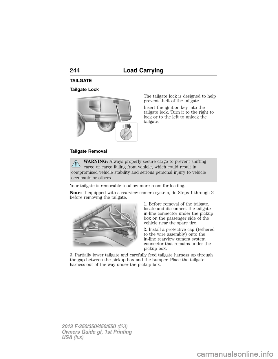
The tailgate lock is designed to help
prevent theft of the tailgate.
Insert the ignition key into the
tailgate lock. Turn it to the right to
lock or to the left to unlock the
tailgate.
Tailgate Removal
WARNING:Always properly secure cargo to prevent shifting
cargo or cargo falling from vehicle, which could result in
compromised vehicle stability and serious personal injury to vehicle
occupants or others.
Your tailgate is removable to allow more room for loading.
Note:If equipped with a rearview camera system, do Steps 1 through 3
before removing the tailgate.
1. Before removal of the tailgate,
locate and disconnect the tailgate
in-line connector under the pickup
box on the passenger side of the
vehicle near the spare tire.
2. Install a protective cap (tethered
to the wire assembly) onto the
in-line rearview camera system
connector that remains under the
pickup box.
3. Partially lower tailgate and carefully feed tailgate harness up through
the gap between the pickup box and the bumper. Place the tailgate
harness out of the way under the pickup box.
244Load Carrying
2013 F-250/350/450/550(f23)
Owners Guide gf, 1st Printing
USA(fus)
Page 272 of 563

ROADSIDE ASSISTANCE
Vehicles Sold in the U.S. : Getting Roadside Assistance
To fully assist you should you have a vehicle concern, Ford Motor
Company offers a complimentary roadside assistance program. This
program is separate from the New Vehicle Limited Warranty. The service
is available:
•24-hours a day, seven days a week
•for the coverage period listed on the Roadside Assistance Card
included in your owner’s manual portfolio.
Roadside assistance will cover:
•a flat tire change with a good spare (except vehicles that have been
supplied with a tire inflation kit).
•battery jump start.
•lock-out assistance (key replacement cost is the customer’s
responsibility).
•fuel delivery – Independent Service Contractors, if not prohibited by
state, local or municipal law shall deliver up to 2.0 gallons (7.5 liters)
of gasoline or 5.0 gallons (18.9 liters) of diesel fuel to a disabled
vehicle. Fuel delivery service is limited to two no-charge occurrences
within a 12-month period.
•winch out – available within 100 feet (30.5 meters) of a paved or
county maintained road, no recoveries.
•towing – Ford and Lincoln eligible vehicles towed to an authorized
dealer within 35 miles (56 kilometers) of the disablement location or
to the nearest authorized dealer. If a member requests to be towed to
an authorized dealer more than 35 miles (56 kilometers) from the
disablement location, the member shall be responsible for any mileage
costs in excess of 35 miles (56 kilometers).
Trailers shall be covered up to $200 if the disabled eligible vehicle
requires service at the nearest authorized dealer. If the trailer is disabled,
but the towing vehicle is operational, the trailer does not qualify for any
roadside services.
Roadside Emergencies271
2013 F-250/350/450/550(f23)
Owners Guide gf, 1st Printing
USA(fus)
Page 274 of 563

HAZARD FLASHER CONTROL
Note:With extended use, the flasher may run down your battery.
The hazard flasher is located on the
steering column, just behind the
steering wheel. The hazard flashers
will operate when the ignition is in
any position or if the key is not in
the ignition.
•Press the flasher control and all
front and rear direction signals
flash.
•Press the flasher control again to turn them off.
Use it when your vehicle is disabled and is creating a safety hazard for
other motorists.
FUEL CUT-OFF SWITCH
WARNING:Failure to inspect and if necessary repair fuel leaks
after a collision may increase the risk of fire and serious injury.
Ford Motor Company recommends that the fuel system be inspected by
an authorized dealer after any collision.
In the event of a moderate to severe collision, this vehicle is equipped
with a fuel pump shut-off feature that stops the flow of fuel to the
engine. Not every impact will cause a shut-off.
Should your vehicle shut off after a collision, you may restart your
vehicle by doing the following:
1. Turn the ignition off.
2. Turn the ignition on.
3. Repeat steps 1 and 2 to re-enable fuel pump.
Note:If your vehicle has the push button start system, press the
stop/start button twice to reactivate the fuel system.
Roadside Emergencies273
2013 F-250/350/450/550(f23)
Owners Guide gf, 1st Printing
USA(fus)
Page 293 of 563

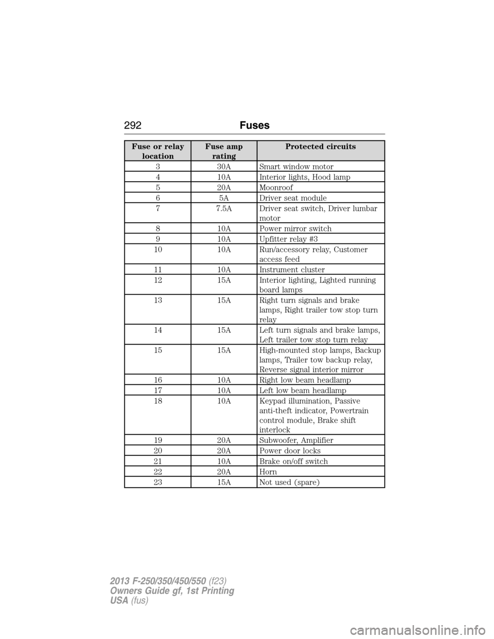
Fuse or relay
locationFuse amp
ratingProtected circuits
3 30A Smart window motor
4 10A Interior lights, Hood lamp
5 20A Moonroof
6 5A Driver seat module
7 7.5A Driver seat switch, Driver lumbar
motor
8 10A Power mirror switch
9 10A Upfitter relay #3
10 10A Run/accessory relay, Customer
access feed
11 10A Instrument cluster
12 15A Interior lighting, Lighted running
board lamps
13 15A Right turn signals and brake
lamps, Right trailer tow stop turn
relay
14 15A Left turn signals and brake lamps,
Left trailer tow stop turn relay
15 15A High-mounted stop lamps, Backup
lamps, Trailer tow backup relay,
Reverse signal interior mirror
16 10A Right low beam headlamp
17 10A Left low beam headlamp
18 10A Keypad illumination, Passive
anti-theft indicator, Powertrain
control module, Brake shift
interlock
19 20A Subwoofer, Amplifier
20 20A Power door locks
21 10A Brake on/off switch
22 20A Horn
23 15A Not used (spare)
292Fuses
2013 F-250/350/450/550(f23)
Owners Guide gf, 1st Printing
USA(fus)
Page 294 of 563

Fuse or relay
locationFuse amp
ratingProtected circuits
24 15A Steering wheel control module,
Diagnostic connector, Power fold
mirror relay, Remote keyless
entry, Electronic finish panel
25 15A Not used (spare)
26 5A Steering wheel control module
27 20A Not used (spare)
28 15A Ignition switch
29 20A SYNC, GPS module, Radio
faceplate
30 15A Parking lamp relay, Trailer tow
parking lamp relay
31 5A Trailer brake controller (brake
signal), Customer access
32 15A Moonroof motor, Telescoping
mirror switch, Auto dimming
mirrors, Power inverter, Driver
and passenger door lock switch
illumination, Rear heated seat
switch illumination
33 10A Restraint control module
34 10A Heated steering wheel module,
Rear heated seats module
35 5A Select shift switch, Reverse park
aid module, Trailer brake control
module
36 10A Fuel tank select switch
37 10A PTC heater
38 10A AM/FM radio faceplate
39 15A High beam headlamps
40 10A Parking lamps (in mirrors), Roof
marker lamps
Fuses293
2013 F-250/350/450/550(f23)
Owners Guide gf, 1st Printing
USA(fus)
Page 295 of 563

Fuse or relay
locationFuse amp
ratingProtected circuits
41 7.5A Passenger airbag deactivation
indicator
42 5A Not used (spare)
43 10A Wiper relay
44 10A Upfitter switches
45 5A Not used (spare)
46 10A Climate control
47 15A Fog lamps, Fog lamp indicator (in
switch)
48 30A Circuit
BreakerPower windows switch, Power
rear sliding window switch
49 Relay Delayed accessory
UPFITTER CONTROLS (IF EQUIPPED)
The upfitter option package
provides four switches, mounted in
the center of the instrument panel.
These switches will only operate
while the ignition is in the on
position, whether the engine is
running or not. However, it is
recommended that the engine
remain running to maintain battery charge when using the upfitter
switches for extended duration or higher current draws. (This is even
more important for vehicles with diesel engines since the glow plugs are
also draining battery power when the ignition key is in the on position.)
When switched on, they provide 8 amps, 12 amps or 20 amps of
electrical battery power for a variety of personal or commercial uses.
There will also be a relay box located on the driver side end of the
instrument panel. See your authorized dealer for service.
AUX 1
AUX 2
AUX 3
AUX 4
294Fuses
2013 F-250/350/450/550(f23)
Owners Guide gf, 1st Printing
USA(fus)