2013 FORD EXPEDITION suspension
[x] Cancel search: suspensionPage 239 of 497

AIR SUSPENSION SYSTEM (IF EQUIPPED)
WARNING:On vehicles equipped with air suspension, turn the
air suspension and the ignition switch off prior to jacking,
hoisting or towing your vehicle.
The air suspension system is designed to improve ride, handling and
general vehicle performance during:
•Certain road conditions
•Steering maneuvers
•Braking
•Acceleration
This system keeps the rear of your vehicle at a constant level by
automatically adding air or releasing air from the springs. If you exceed
the load limit, the rear air suspension may not operate. The air
suspension system will stay active for 40 minutes after the ignition is
turned off to accommodate any load changes. (The air compressor may
run when the vehicle is off; this is normal.)
The air suspension system can be enabled or disabled through the
message center. Refer to theInformation Displayschapter.
If the system is off, the rear air suspension will not operate and will not
raise (pump) or lower (vent) while the vehicle is not moving. However, if
the system determines that the vehicle is low or high and needs to make
a height adjustment while driving at speeds above 15 mph (24 km/h), the
system will pump or vent as required. Normal vehicle operation does not
require any action by the driver.
Driving Aids239
2013 Expedition(exd)
Owners Guide gf, 1st Printing
USA(fus)
Page 251 of 497

TOWING A TRAILER
WARNING:Do not exceed the GVWR or the GAWR specified on
the certification label.
WARNING:Towing trailers beyond the maximum recommended
gross trailer weight exceeds the limit of the vehicle and could
result in engine damage, transmission damage, structural damage, loss
of vehicle control, vehicle rollover and personal injury.
Note:For information on electrical items such as fuses or relays, see the
Fuseschapter.
Your vehicle’s load capacity is designated by weight, not by volume, so
you cannot necessarily use all available space when loading a vehicle.
Towing a trailer places an additional load on your vehicle’s engine,
transmission, axle, brakes, tires and suspension. Inspect these
components periodically during, and after, any towing operation.
When driving with a trailer or payload, a slight takeoff vibration or
shudder may be present due to the increased payload weight. Additional
information regarding proper trailer loading and setting your vehicle up
for towing is noted underLoad limitin theLoad Carryingchapter and
in theRV & Trailer Towing Guide,available at your authorized dealer.
Load Placement
To help minimize how trailer movement affects the vehicle when driving:
•Load the heaviest items closest to the trailer floor.
•Load the heaviest items so they are centered between the left and
right side trailer tires.
•Load the heaviest items above the trailer axles or just slightly forward
toward the trailer tongue. Do not allow the final trailer tongue weight
to go above or below 10–15% of the loaded trailer weight.
•Select a tow bar with the correct rise or drop. When both the loaded
vehicle and trailer are connected, the trailer frame should be level, or
slightly angled down, when viewed from the side.
TRAILER SWAY CONTROL
Note:This feature does not prevent trailer sway, but reduces it once it
begins.
Note:This feature cannot stop all trailers from swaying.
Note:In some cases, if vehicle speed is too high, the system may
activate multiple times, gradually reducing vehicle speed.
Towing251
2013 Expedition(exd)
Owners Guide gf, 1st Printing
USA(fus)
Page 254 of 497

The standard integrated hitch has two ratings depending on mode of
operation:
•Weight-carryingrequires a draw bar and hitch ball. The draw bar
supports all the vertical tongue load of the trailer.
•Weight-distributingrequires an aftermarket weight-distributing
system which includes draw bar, hitch ball, spring bars and snap-up
brackets. The vertical tongue load of the trailer is distributed between
the truck and the trailer by this system.
Mode Maximum Trailer
Weight - lb (kg)Maximum Tongue
Weight - lb (kg)
Weight-carrying 6000 (2721) 600 (272)
Weight-distributing 9200 (4173) 920 (417)
Note:These are hitch ratings only; actual vehicle ratings are dependent
on engine, transmission and axle combinations.
Weight-distributing Hitch – Vehicles without Air Suspension
WARNING:Do not adjust a weight-distributing hitch to any
position where the rear bumper of the vehicle is higher than it
was before attaching the trailer. Doing so will defeat the function of the
weight-distributing hitch, which may cause unpredictable handling, and
could result in serious personal injury.
When hooking-up a trailer using a weight-distributing hitch, always use
the following procedure:
1. Park the vehicle (without the trailer) on a level surface.
2. Measure the height of the top of the front wheel opening on the
fender, this is H1.
3. Attach the trailer to the vehicle without the weight distributing bars
connected.
4. Measure the height of the top of the front wheel opening on the
fender a second time, this is H2.
5. Install and adjust the tension in the weight distributing bars so that
the height of the front fender is approximately halfway between H1
and H2.
6. Check that the trailer is level. If not level, remove the trailer, adjust
the ball height accordingly, and repeat Steps 3–6.
254Towing
2013 Expedition(exd)
Owners Guide gf, 1st Printing
USA(fus)
Page 255 of 497

Weight-distributing Hitch – Vehicles with Air Suspension
WARNING:Do not adjust a weight-distributing hitch to any
position where the rear bumper of the vehicle is higher than it
was before attaching the trailer. Doing so will defeat the function of the
weight-distributing hitch, which may cause unpredictable handling, and
could result in serious personal injury.
When hooking-up a trailer using a weight-distributing hitch, always use
the following procedure:
1. Turn off easy entry / kneel feature if equipped.
2. Park the vehicle, without trailer and with the ignition on, on a level
surface with all doors closed for a few minutes to ensure that the air
suspension has settled.
3. Measure the height of the top of the front wheel opening on the
fender, this is H1.
4. Attach the trailer to the vehicle; do not install the weight distributing
bars at this time.
5. With the ignition on and all doors closed, let the vehicle with trailer
sit for a few minutes to let the air suspension re-settle.
6. With the trailer connected, but without weight distributing bars
connected, measure the height of the top of the front wheel opening
on the fender a second time, this is H2.
7. Install and adjust the tension in the weight distributing bars so that
the height of the front fender is approximately halfway between H1
and H2.
8. With the ignition on and all doors closed, let the vehicle, now with
trailer and weight distributing bars connected, sit for a few minutes
to let the air suspension re-settle.
9. Re-measure the height of the top of the front wheel opening,
repeating Steps 7-9 as necessary to obtain a fender height
approximately halfway between H1 and H2 after the air suspension
has settled.
10. Check that the trailer is level. If not level, remove the trailer, adjust
the ball height accordingly, and repeat Steps 4–10.
Safety Chains
Note:Do not attach safety chains to the bumper.
Always connect the trailer’s safety chains to the frame or hook retainers
of the vehicle hitch.
To connect the trailer’s safety chains, cross the chains under the trailer
tongue and allow enough slack for turning tight corners. Do not allow the
chains to drag on the ground.
Towing255
2013 Expedition(exd)
Owners Guide gf, 1st Printing
USA(fus)
Page 262 of 497

Replace the rear axle lubricant anytime the rear axle has been
submerged in water. Water may have contaminated the rear axle
lubricant, which is not normally checked or changed unless a leak is
suspected or other axle repair is required.
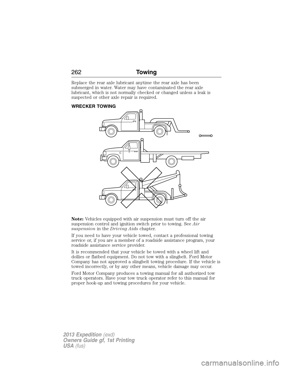
WRECKER TOWING
Note:Vehicles equipped with air suspension must turn off the air
suspension control and ignition switch prior to towing. SeeAir
suspensionin theDriving Aidschapter.
If you need to have your vehicle towed, contact a professional towing
service or, if you are a member of a roadside assistance program, your
roadside assistance service provider.
It is recommended that your vehicle be towed with a wheel lift and
dollies or flatbed equipment. Do not tow with a slingbelt. Ford Motor
Company has not approved a slingbelt towing procedure. If the vehicle is
towed incorrectly, or by any other means, vehicle damage may occur.
Ford Motor Company produces a towing manual for all authorized tow
truck operators. Have your tow truck operator refer to this manual for
proper hook-up and towing procedures for your vehicle.
262Towing
2013 Expedition(exd)
Owners Guide gf, 1st Printing
USA(fus)
Page 283 of 497

Fuse/Relay
LocationFuse Amp
RatingProtected Circuits
4 — Trailer tow battery charge relay
5 — Fuel pump relay
6 — Electronic fan 1 relay
7 — Rear window defroster/heated
mirror relay
8 — Electronic fan 3 relay
9 — Run/start relay
10 — Rear air suspension relay
11 40A** Power running board
12 40A** Run/start relay
13 30A ** Starter relay
14 40A** Electronic fan
15 — Not used
16 40A** Electronic fan
17 — Not used
18 30A** Trailer brake
19 60A** Rear air suspension relay feed
20 20A** 4x4 module
21 30A** Trailer tow battery charge relay
22 30A** Passenger power seat
23 — A/C clutch relay
24 — Trailer tow park lamp relay
25 — Not used
26 — Not used
27 20A* 4x4
28 25A* Trailer tow park lamp relay
29 20A* Backup lamps, Integrated wheel
end solenoid
30 10A* A/C clutch relay
31 — Not used
32 40A** Blower motor relay
Fuses283
2013 Expedition(exd)
Owners Guide gf, 1st Printing
USA(fus)
Page 284 of 497

Fuse/Relay
LocationFuse Amp
RatingProtected Circuits
33 40A** 110 volt AC power point
34 30A** Auxiliary blower motor
35 30A** Powertrain control module relay
36 30A** Power liftgate
37 — Trailer tow left hand stop/turn
relay
38 — Trailer tow right hand stop/turn
relay
39 — Backup lamps relay
40 — Electronic fan 2 relay
41 10A* Powertrain control module
keep-alive power
42 — Not used
43 5A* Brake on/off switch
44 20A* Fuel pump relay
45 25A* Trailer tow stop/turn lamps relay
46 — Not used
47 — Not used
48 30A** Rear air suspension module
49 — Not used
50 30A** Front wiper motor relay
51 40A** Rear window defroster/heated
mirror relay
52 10A* Anti-lock brake system run/start
feed
53 10A* Rear air suspension module
54 — Not used
55 5A* Fuel pump relay coil run/start
feed
56 30A* Passenger compartment fuse
panel R/S feed
57 10A* Blower motor relay coil
284Fuses
2013 Expedition(exd)
Owners Guide gf, 1st Printing
USA(fus)
Page 306 of 497

ADJUSTING THE HEADLAMPS
The headlamps on your vehicle are properly aimed at the assembly plant.
If your vehicle has been in an accident, the alignment of your headlamps
should be checked by your authorized dealer.
Vertical Aim Adjustment
Before aim adjustment, disable the air suspension system. Refer to
Message centerin theDriver Controlschapter.
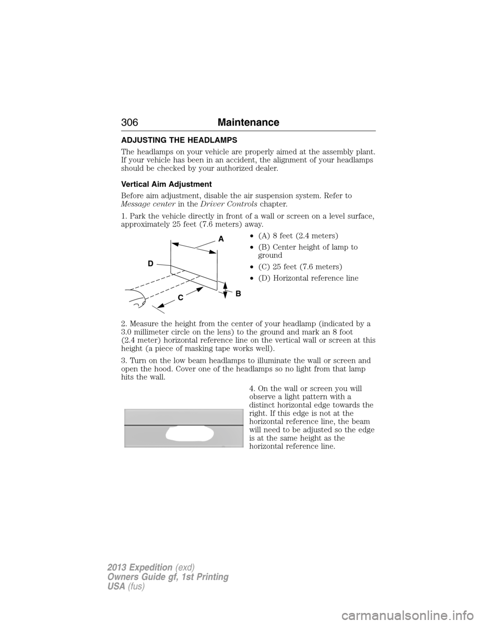
1. Park the vehicle directly in front of a wall or screen on a level surface,
approximately 25 feet (7.6 meters) away.
•(A) 8 feet (2.4 meters)
•(B) Center height of lamp to
ground
•(C) 25 feet (7.6 meters)
•(D) Horizontal reference line
2. Measure the height from the center of your headlamp (indicated by a
3.0 millimeter circle on the lens) to the ground and mark an 8 foot
(2.4 meter) horizontal reference line on the vertical wall or screen at this
height (a piece of masking tape works well).
3. Turn on the low beam headlamps to illuminate the wall or screen and
open the hood. Cover one of the headlamps so no light from that lamp
hits the wall.
4. On the wall or screen you will
observe a light pattern with a
distinct horizontal edge towards the
right. If this edge is not at the
horizontal reference line, the beam
will need to be adjusted so the edge
is at the same height as the
horizontal reference line.
C
A
B
D
306Maintenance
2013 Expedition(exd)
Owners Guide gf, 1st Printing
USA(fus)