Page 105 of 140

8-25
8
NOTICEECB01160Brake fluid may damage painted surfaces or
plastic parts. Always clean up spilled fluid im-
mediately.As the brake pads wear, it is normal for the brake
fluid level to gradually go down. A low brake fluid
level may indicate worn brake pads and/or brake
system leakage; therefore, be sure to check the
brake pads for wear and the brake system for leak-
age. If the brake fluid level goes down suddenly,
have a Yamaha dealer check the cause before fur-
ther riding.EBU24291Changing the brake fluid Have a Yamaha dealer change the brake fluid at
the intervals specified in the TIP after the periodic
maintenance and lubrication chart. In addition,
have the oil seals of the master cylinders and cali-
pers as well as the brake hoses replaced at the in-
tervals listed below or whenever they are damaged
or leaking.�Oil seals: Replace every two years.�Brake hoses: Replace every four years.
EBU24394Checking the front brake lever free play The brake lever free play must be checked at the
intervals specified in the periodic maintenance and
lubrication chart. The brake lever should have no
free play as shown. If there is free play, have a
Yamaha dealer check the brake system.EBU24593Checking the brake pedal height The brake pedal height must be checked and, if
necessary, adjusted at the intervals specified in the
periodic maintenance and lubrication chart.1. No brake lever free play
U1BS62E0.book Page 25 Monday, April 18, 2011 6:43 PM
Page 106 of 140
8-26
8The top of the brake pedal should be positioned
50.2 mm (1.98 in) above the top of the frame as
shown. If the brake pedal is not positioned as spec-
ified, have a Yamaha dealer adjust it.
EBU24713Adjusting the parking brake free play The parking brake free play must be checked and,
if necessary, adjusted at the intervals specified in
the periodic maintenance and lubrication chart.
Cable length “
A” should measure 64 –68 mm
(2.52 –2.68 in). Adjust the parking brake free play
as follows. 1. Release the parking brake by moving the
parking brake lever to the right.
2. Fully loosen the locknut and the adjusting bolt at the rear brake caliper.
3. Slide the rubber cover back at the brake ca- ble.
4. Loosen the locknut.
5. Turn the adjusting nut on the brake cable in di- rection (a) to increase the cable length, and in
direction (b) to decrease it.1. Brake pedal height
1. Locknut
2. Adjusting bolt
3. Cable length “A ”
U1BS62E0.book Page 26 Monday, April 18, 2011 6:43 PM
Page 107 of 140

8-27
8
TIPIf the cable length cannot be adjusted to specifica-
tion, consult a Yamaha dealer.6. Tighten the locknut on the brake cable.
7. Slide the rubber cover to its original position.
8. Turn in the adjusting bolt at the rear brake cal-iper until it feels tight, then turn it out 1/8 turn
and tighten its locknut to the specified torque.
NOTICE: When tightening the locknut, hold the adjusting bolt with a wrench so
that it does not turn together with the lock-
nut.
[ECB00521]
WARNING
EWB02090Operating with improperly serviced or adjust-
ed brakes could cause the brakes to malfunc-
tion, resulting in reduced braking
performance. This could increase the chance
of a collision or accident. After adjusting the
parking brake free play, block the rear of the
ATV off the ground and spin the rear wheels.
Check to make sure there is no brake drag. If
brake drag is noticed, perform the adjustment
again.EBU24743Brake light switches The brake light, which is activated by the brake
pedal and brake lever, should come on just before
braking takes effect.
1. Locknut
2. Adjusting nut
3. Rubber cover
1
2
(a) (b)
3
Tightening torque:
Locknut (rear brake caliper):16 Nm (1.6 m ·kgf, 12 ft ·lbf)
U1BS62E0.book Page 27 Monday, April 18, 2011 6:43 PM
Page 108 of 140

8-28
8The brake light switch for the brake pedal can be
adjusted as follows, but the front brake light switch
should be adjusted by a Yamaha dealer.
Turn the rear brake light switch adjusting nut while
holding the brake light switch in place. To make the
brake light come on earlier, turn the adjusting nut
in direction (a). To make the brake light come on
later, turn the adjusting nut in direction (b).
EBU30120Adjusting the clutch lever free play The clutch lever free play must be checked and, if
necessary, adjusted at the intervals specified in the
periodic maintenance and lubrication chart. The clutch lever free play should measure 5.0–
10.0 mm (0.20
–0.39 in) as shown. If the free play
is incorrect, adjust it as follows. 1. Slide the rubber cover back at the clutch lever.
2. Loosen the locknut.
3. To increase the clutch lever free play, turn the adjusting bolt at the clutch lever in direction
(a), and to decrease it, turn the bolt in direction
(b).1. Rear brake light switch
2. Rear brake light switch adjusting nut
1. Clutch lever free play
2. Rubber cover
3. Locknut
4. Clutch lever free play adjusting bolt
3
2
4
(a)
(b)
1
U1BS62E0.book Page 28 Monday, April 18, 2011 6:43 PM
Page 109 of 140
 to loosen the clutch ca")
8-29
8
TIPIf the specified clutch lever free play could be ob-
tained as described above, skip steps 4–8.4. Fully turn the adjusting bolt at the clutch lever
in direction (a) to loosen the clutch cable.
5. Slide the rubber cover back at the crankcase.
6. Loosen the locknut.
7. To increase the clutch lever free play, turn the adjusting nut at the crankcase in direction (a),
and to decrease it, turn the nut in direction (b). 8. Tighten the locknut at the crankcase, and then
slide the rubber cover to its original position.
9. Tighten the locknut at the clutch lever, and then slide the rubber cover to its original posi-
tion.
TIPIf the specified free play cannot be obtained as de-
scribed above or if the clutch does not operate cor-
rectly, have a Yamaha dealer check the internal
clutch mechanism.EBU24845Drive chain slack The drive chain slack should be checked before
each ride and adjusted if necessary.
To check the drive chain slack1. Place the ATV on a level surface.TIPWhen checking and adjusting the drive chain
slack, there should be no weight on the ATV and
all tires must be touching the ground.2. Move the ATV back and forth to locate the tightest portion of the drive chain, and then
measure the drive chain slack as shown.
1. Locknut
2. Clutch lever free play adjusting nut (crankcase)
3. Rubber cover
2
(a)
(b)
3
1
U1BS62E0.book Page 29 Monday, April 18, 2011 6:43 PM
Page 110 of 140
8-30
83. If the drive chain slack is incorrect, adjust it as
follows.
To adjust the drive chain slack 1. Place the ATV on a level surface.
2. Loosen the axle holding bolts. 3. Loosen the locknut on each side of the swing-
arm. To tighten the drive chain, turn the drive
chain slack adjusting bolts in direction (a). To
loosen the drive chain, turn the adjusting bolts
in direction (b) and push the wheels forward.
Turn each adjusting bolt exactly the same
amount to maintain correct axle alignment.
NOTICE: Improper drive chain slack will
overload the engine as well as other vital
parts of the ATV and can lead to drive
chain slippage or breakage. To prevent
this from occurring, keep the drive chain
slack within the specified limits.
[ECB00542]
Drive chain slack: 25.0 –35.0 mm (0.98 –1.38 in)1. Drive chain slack
1. Axle holding bolt (upper)
2. Axle holding bolt (lower)
U1BS62E0.book Page 30 Monday, April 18, 2011 6:43 PM
Page 111 of 140

8-31
8
TIPThere are alignment marks on both drive chain
pullers and an alignment mark on each side of the
swingarm. Make sure to align the same alignment
mark on both drive chain pullers with the alignment
mark on either side of the swingarm for proper
wheel alignment.4. Tighten the locknuts and the axle holding boltsto the specified torques.
EBU24882Lubricating the drive chain The drive chain must be cleaned and lubricated at
the intervals specified in the periodic maintenance
and lubrication chart, otherwise it will quickly wear
out, especially when riding in dusty or wet areas.
Service the drive chain as follows.NOTICEECB00561The drive chain must be lubricated after wash-
ing the ATV or riding in the rain or wet areas.1. Clean the drive chain with kerosene and asmall soft brush. NOTICE: To prevent dam-
aging the O-rings, do not clean the drive
chain with steam cleaners, high-pressure
washers or inappropriate solvents.
[ECB00571]
1. Locknut
2. Drive chain slack adjusting bolt
3. Alignment marks
Tightening torques: Locknut:16 Nm (1.6 m ·kgf, 12 ft ·lbf)
Axle holding bolt (upper): 120 Nm (12 m· kgf, 87 ft·lbf)
Axle holding bolt (lower): 73 Nm (7.3 m ·kgf, 53 ft ·lbf)
U1BS62E0.book Page 31 Monday, April 18, 2011 6:43 PM
Page 112 of 140

8-32
82. Wipe the drive chain dry.
3. Thoroughly lubricate the drive chain with a
special O-ring chain lubricant. NOTICE: Do
not use engine oil or any other lubricants
for the drive chain, as they may contain
substances that could damage the O-
rings.
[ECB00581]
EBU24902
Checking and lubricating the cables The operation and the condition of all control ca-
bles should be checked before each ride, and the
cables and cable ends should be lubricated if nec- essary. If a cable is damaged or does not move
smoothly, have a Yamaha dealer check or replace
it.
WARNING
EWB02581�Inspect cables frequently and replace if dam-
aged. Corrosion can result when the cable
sheaths become damaged, and cables can
also become frayed or kinked, which could
restrict the operation of controls and lead to
an accident or injury.�Always make sure all control cables work
smoothly before you begin riding in cold
weather. If the control cables are frozen or do
not work smoothly, you could be unable to
control the ATV, which could lead to an acci-
dent or collision.
1. O-ring
1
1
Recommended lubricant:
Yamaha Chain and Cable Lube or engine oil
U1BS62E0.book Page 32 Monday, April 18, 2011 6:43 PM
 1
1 2
2 3
3 4
4 5
5 6
6 7
7 8
8 9
9 10
10 11
11 12
12 13
13 14
14 15
15 16
16 17
17 18
18 19
19 20
20 21
21 22
22 23
23 24
24 25
25 26
26 27
27 28
28 29
29 30
30 31
31 32
32 33
33 34
34 35
35 36
36 37
37 38
38 39
39 40
40 41
41 42
42 43
43 44
44 45
45 46
46 47
47 48
48 49
49 50
50 51
51 52
52 53
53 54
54 55
55 56
56 57
57 58
58 59
59 60
60 61
61 62
62 63
63 64
64 65
65 66
66 67
67 68
68 69
69 70
70 71
71 72
72 73
73 74
74 75
75 76
76 77
77 78
78 79
79 80
80 81
81 82
82 83
83 84
84 85
85 86
86 87
87 88
88 89
89 90
90 91
91 92
92 93
93 94
94 95
95 96
96 97
97 98
98 99
99 100
100 101
101 102
102 103
103 104
104 105
105 106
106 107
107 108
108 109
109 110
110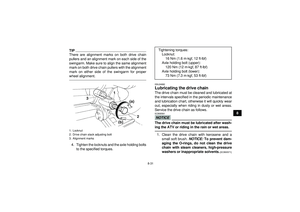 111
111 112
112 113
113 114
114 115
115 116
116 117
117 118
118 119
119 120
120 121
121 122
122 123
123 124
124 125
125 126
126 127
127 128
128 129
129 130
130 131
131 132
132 133
133 134
134 135
135 136
136 137
137 138
138 139
139 above the top of the frame as
shown. If the brake pedal is not positioned as spec-
ified, have a Yamaha dealer adjust it.
EBU247")
