Page 65 of 82
PERIODIC MAINTENANCE AND ADJUSTMENT
7-24
7
NOTICE
ECA16530
Always keep the battery charged.
Storing a discharged battery can
cause permanent battery damage.
EAU42024
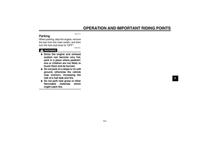
Replacing the fuse The fuse is located inside the battery
coupler.
If the fuse is blown, replace it as fol-
lows.
1. Turn the key to “OFF” and turn off
all electrical circuits.
2. Remove the seat. (See page 4-7.)
3. Remove the battery cover by re-
moving the bolts.4. Disconnect the battery coupler.
5. Remove the blown fuse, and then
install a new fuse of the specified
amperage. WARNING! Do not
use a fuse of a higher amperage1. Battery coupler
2. Spare fuse
3. Fuse
32
1
1. Bolt
2. Battery
3. Battery cover
1. Battery coupler
1
U1P686E0.book Page 24 Thursday, April 14, 2011 1:20 PM
Page 66 of 82
![YAMAHA TTR50 2012 Owners Manual PERIODIC MAINTENANCE AND ADJUSTMENT
7-25
7rating than recommended to
avoid causing extensive dam-
age to the electrical system and
possibly a fire.
[EWA15131]
6. Connect the battery coupler.
7. Insta](/manual-img/51/51663/w960_51663-65.png "YAMAHA TTR50 2012 Owners Manual PERIODIC MAINTENANCE AND ADJUSTMENT
7-25
7rating than recommended to
avoid causing extensive dam-
age to the electrical system and
possibly a fire.
[EWA15131]
6. Connect the battery coupler.
7. Insta")
PERIODIC MAINTENANCE AND ADJUSTMENT
7-25
7rating than recommended to
avoid causing extensive dam-
age to the electrical system and
possibly a fire.
[EWA15131]
6. Connect the battery coupler.
7. Install the battery cover by install-
ing the bolts.
8. Install the seat.
9. Turn the key to “ON”.
10. If the fuse immediately blows
again, have a Yamaha dealer
check the electrical system.
EAU24350
Supporting the motorcycle Since this model is not equipped with a
centerstand, follow these precautions
when removing the front and rear
wheel or performing other maintenance
requiring the motorcycle to stand up-
right. Check that the motorcycle is in a
stable and level position before starting
any maintenance. A strong wooden
box can be placed under the engine for
added stability.
To service the front wheel
1. Stabilize the rear of the motorcycle
by using a motorcycle stand or, if
an additional motorcycle stand is
not available, by placing a jack un-
der the frame in front of the rear
wheel.
2. Raise the front wheel off the
ground by using a motorcycle
stand.
To service the rear wheel
Raise the rear wheel off the ground by
using a motorcycle stand or, if a motor-
cycle stand is not available, by placinga jack either under each side of the
frame in front of the rear wheel or under
each side of the swingarm.
Specified fuse:
10.0 A
U1P686E0.book Page 25 Thursday, April 14, 2011 1:20 PM
Page 67 of 82

PERIODIC MAINTENANCE AND ADJUSTMENT
7-26
7
EAU24360
Front wheel
EAU39793
To remove the front wheel
WARNING
EWA10821
To avoid injury, securely support the
vehicle so there is no danger of it
falling over.1. Remove the guard from each front
fork leg by removing the bolts.
2. Disconnect the brake cable at the
wheel by removing the brake lever
free play adjusting nut at the brakecamshaft lever, then remove the
cable from the brake camshaft le-
ver.
3. Loosen the axle nut.4. Lift the front wheel off the ground
according to the procedure in the
previous section “Supporting the
motorcycle”.
5. Remove the axle nut and washer.
6. Pull the wheel axle out, and then
remove the wheel.
EAU39802
To install the front wheel
1. Lift the wheel up between the fork
legs.
2. Insert the wheel axle from the
right-hand side.TIPMake sure that the slot in the brake
shoe plate fits over the retainer on the
fork leg.
1. Front fork leg guard
2. Bolt
1. Brake cable
2. Brake camshaft lever
3. Brake lever free play adjusting nut
1. Axle nut
2. Washer
1. Wheel axle
U1P686E0.book Page 26 Thursday, April 14, 2011 1:20 PM
Page 68 of 82

PERIODIC MAINTENANCE AND ADJUSTMENT
7-27
73. Lower the front wheel so that it is
on the ground, and then put the
sidestand down.
4. Install the washer and axle nut,
and then tighten the axle nut to the
specified torque.
5. Connect the brake cable to the
brake camshaft lever, and then in-
stall the brake cable free play ad-
justing nut on the brake cable.
6. Adjust the brake lever free play.
(See page 7-15.)7. While applying the front brake,
push down hard on the handlebar
several times to check for proper
fork operation.
8. Install each front fork leg guard by
installing the bolts.
EAU25080
Rear wheel
EAU39774
To remove the rear wheel
WARNING
EWA10821
To avoid injury, securely support the
vehicle so there is no danger of it
falling over.1. Loosen the axle nut.
2. Remove the brake pedal free play
adjusting nut, and then disconnect
the brake rod from the brake cam-
shaft lever.
1. Slot
2. RetainerTightening torque:
Axle nut:
35 Nm (3.5 m·kgf, 25 ft·lbf)
2
1
1. Axle nut
2. Washer
3. Drive chain slack adjusting nut
4. Locknut
5. Drive chain puller
1
5
4
3
2
U1P686E0.book Page 27 Thursday, April 14, 2011 1:20 PM
Page 69 of 82

PERIODIC MAINTENANCE AND ADJUSTMENT
7-28
7 3. Fully loosen the locknut and drive
chain slack adjusting nut on each
end of the swingarm.
4. Lift the rear wheel off the ground
according to the procedure on
page 7-25.
5. Remove the axle nut, washer and
the drive chain puller at the left-
hand side, then pull the wheel axle
out together with the drive chain
puller from the right-hand side.6. Push the wheel forward, and then
remove the drive chain from the
rear sprocket.
TIPThe drive chain does not need to be
disassembled in order to remove and
install the wheel.
7. Remove the wheel.
EAU39783
To install the rear wheel
1. Install the drive chain onto the rear
sprocket, lift the rear wheel off the
ground, and then install the drive
chain puller and the wheel by in-
serting the wheel axle from the
right-hand side.TIPMake sure that the slot in the brake
shoe plate fits over the retainer on the
swingarm.2. Install the drive chain puller, wash-
er and axle nut.
1. Brake pedal free play adjusting nut
2. Brake rod
3. Brake camshaft lever
1
2
3
1. Wheel axle
1. Slot
2. Retainer
U1P686E0.book Page 28 Thursday, April 14, 2011 1:20 PM
Page 70 of 82

PERIODIC MAINTENANCE AND ADJUSTMENT
7-29
73. Connect the brake rod to the brake
camshaft lever, and then install the
brake pedal free play adjusting nut
onto the brake rod.
4. Lower the rear wheel so that it is
on the ground, and then put the
sidestand down.
5. Adjust the drive chain slack. (See
page 7-17.)
6. Tighten the axle nut to the speci-
fied torque.
7. Adjust the brake pedal free play.
(See page 7-16.)
EAU25851
Troubleshooting Although Yamaha motorcycles receive
a thorough inspection before shipment
from the factory, trouble may occur dur-
ing operation. Any problem in the fuel,
compression, or ignition systems, for
example, can cause poor starting and
loss of power.
The following troubleshooting chart
represents a quick and easy procedure
for checking these vital systems your-
self. However, should your motorcycle
require any repair, take it to a Yamaha
dealer, whose skilled technicians have
the necessary tools, experience, and
know-how to service the motorcycle
properly.
Use only genuine Yamaha replace-
ment parts. Imitation parts may look like
Yamaha parts, but they are often inferi-
or, have a shorter service life and can
lead to expensive repair bills.
WARNING
EWA15141
When checking the fuel system, do
not smoke, and make sure there are
no open flames or sparks in the ar-
ea, including pilot lights from waterheaters or furnaces. Gasoline or
gasoline vapors can ignite or ex-
plode, causing severe injury or
property damage.
Tightening torque:
Axle nut:
60 Nm (6.0 m·kgf, 43 ft·lbf)
U1P686E0.book Page 29 Thursday, April 14, 2011 1:20 PM
Page 71 of 82

PERIODIC MAINTENANCE AND ADJUSTMENT
7-30
7
EAU25903
Troubleshooting chart
Check the fuel level in
the fuel tank.1. Fuel
There is enough fuel.
There is no fuel.
Check the compression.
Supply fuel.
The engine does not start.
Check the compression.
Operate the electric starter.2. Compression
There is compression.
There is no compression.
Check the ignition.
Have a Yamaha dealer
check the vehicle.
Remove the spark plug
and check the electrodes.3. Ignition
Wipe off with a dry cloth and correct the
spark plug gap, or replace the spark plug.
Have a Yamaha dealer check the vehicle.
The engine does not start.
Have a Yamaha dealer
check the vehicle.
The engine does not start.
Check the battery.
Operate the electric starter.4. Battery
The engine turns over
quickly.
The engine turns over
slowly.
The battery is good.Check the battery lead connections,
and have a Yamaha dealer charge
the battery if necessary.
DryWet
Open the throttle halfway and operate
the electric starter.
U1P686E0.book Page 30 Thursday, April 14, 2011 1:20 PM
Page 72 of 82

MOTORCYCLE CARE AND STORAGE
8-1
8
EAU37833
Matte color caution NOTICE
ECA15192
Some models are equipped with
matte colored finished parts. Be
sure to consult a Yamaha dealer for
advice on what products to use be-
fore cleaning the vehicle. Using a
brush, harsh chemical products or
cleaning compounds when cleaning
these parts will scratch or damage
their surface. Wax also should not
be applied to any matte colored fin-
ished parts.
EAU40465
Care While the open design of a motorcycle
reveals the attractiveness of the tech-
nology, it also makes it more vulnera-
ble. Rust and corrosion can develop
even if high-quality components are
used. A rusty exhaust pipe may go un-
noticed on a car, however, it detracts
from the overall appearance of a motor-
cycle. Frequent and proper care does
not only comply with the terms of the
warranty, but it will also keep your mo-
torcycle looking good, extend its life
and optimize its performance.
Before cleaning
1. Cover the muffler outlet with a
plastic bag after the engine has
cooled down.
2. Make sure that all caps and covers
as well as all electrical couplers
and connectors, including the
spark plug cap, are tightly in-
stalled.
3. Remove extremely stubborn dirt,
like oil burnt onto the crankcase,
with a degreasing agent and a
brush, but never apply such prod-ucts onto seals, gaskets, sprock-
ets, the drive chain and wheel
axles. Always rinse the dirt and de-
greaser off with water.
Cleaning
NOTICE
ECA10772
�
Avoid using strong acidic wheel
cleaners, especially on spoked
wheels. If such products are
used on hard-to-remove dirt, do
not leave the cleaner on the af-
fected area any longer than in-
structed. Also, thoroughly rinse
the area off with water, immedi-
ately dry it, and then apply a cor-
rosion protection spray.
�
Improper cleaning can damage
plastic parts (such as cowlings,
panels, windshields, headlight
lenses, meter lenses, etc.) and
the mufflers. Use only a soft,
clean cloth or sponge with wa-
ter to clean plastic. However, if
the plastic parts cannot be thor-
oughly cleaned with water, di-
luted mild detergent with water
may be used. Be sure to rinse
U1P686E0.book Page 1 Thursday, April 14, 2011 1:20 PM