Page 49 of 82

PERIODIC MAINTENANCE AND ADJUSTMENT
7-8
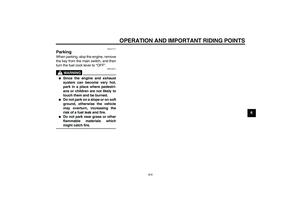
7 3. Remove the engine oil filler cap,
the engine oil drain bolt and its
gasket to drain the oil from the
crankcase.
4. Install a new gasket and the drain
bolt, and then tighten the drain bolt
to the specified torque.
5. Refill with the specified amount of
the recommended engine oil, and
then install and tighten the oil filler
cap.
NOTICE
ECA11620
�
In order to prevent clutch slip-
page (since the engine oil also
lubricates the clutch), do not
mix any chemical additives. Do
not use oils with a diesel speci-
fication of “CD” or oils of a high-
er quality than specified. In
addition, do not use oils labeled
“ENERGY CONSERVING II” or
higher.
�
Make sure that no foreign mate-
rial enters the crankcase.
6. Start the engine, and then let it idle
for several minutes while checking
it for oil leakage. If oil is leaking, im-
mediately turn the engine off and
check for the cause.
7. Turn the engine off, and then
check the oil level and correct it if
necessary.
EAU39834
Cleaning the air filter element The air filter element should be cleaned
as follows at the intervals specified in
the periodic maintenance and lubrica-
tion chart. Clean or, if necessary, re-
place the air filter element more
frequently if you are riding in unusually
wet or dusty areas.
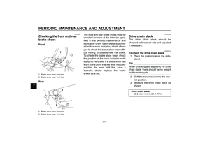
To clean the air filter element
1. Remove the air filter case cover by
removing the screws.
2. Pull the sponge material and the
air filter mesh out.
1. Engine oil drain bolt
2. GasketTightening torque:
Engine oil drain bolt:
20 Nm (2.0 m·kgf, 14 ft·lbf)
12
Recommended engine oil:
See page 9-1.
Oil change quantity:
0.80 L (0.85 US qt, 0.70 Imp.qt)
1. Screw
2. Air filter case cover
U1P686E0.book Page 8 Thursday, April 14, 2011 1:20 PM
Page 50 of 82

PERIODIC MAINTENANCE AND ADJUSTMENT
7-9
7
3. Clean the mesh with solvent, and
then wipe the solvent off.
4. Clean the sponge material with
solvent, and then squeeze the re-
maining solvent out. WARNING!
Use only a dedicated parts
cleaning solvent. To avoid therisk of fire or explosion, do not
use gasoline or solvents with a
low flash point.
[EWA10431]
NOTICE:
To avoid damaging the foam
material, handle it gently and
carefully, and do not twist or
wring it.
[ECA10511]
5. Apply oil of the recommended type
to the entire surface of the sponge
material, and then squeeze the ex-
cess oil out.TIPThe sponge material should be wet but
not dripping.
6. Insert the mesh and the sponge
material into the air filter case.
NOTICE: Make sure that the
mesh and the sponge material
are properly seated in the air fil-
ter case. The engine should
never be operated without the
mesh and the sponge material
installed, otherwise the pis-
ton(s) and/or cylinder(s) may
become excessively worn.
[ECA15572]
7. Install the air filter case cover by in-
stalling the screws.
To clean the air filter check hose
1. Check the hose at the bottom of
the air filter case for accumulated
dirt or water.
1. Sponge material
1. Air filter mesh
Recommended oil:
Yamaha foam air filter oil or other
quality foam air filter oil
U1P686E0.book Page 9 Thursday, April 14, 2011 1:20 PM
Page 51 of 82
PERIODIC MAINTENANCE AND ADJUSTMENT
7-10
7 2. If dirt or water is visible, remove
the hose, clean it, and then install
it.
EAU40421
Cleaning the spark arrester The spark arrester should be cleaned
at the intervals specified in the periodic
maintenance and lubrication chart.
WARNING
EWA10980
�
Always let the exhaust system
cool prior to touching exhaust
components.
�
Do not start the engine when
cleaning the exhaust system.
TIPMake sure to select a well-ventilated
area free of combustible materials to
clean the spark arrester.1. Remove the tailpipe by removing
the bolts, and then pulling it out of
the muffler.2. Tap the tailpipe lightly, and then
use a wire brush to remove any
carbon deposits from the spark ar-
rester portion of the tailpipe and in-
side of the tailpipe housing.
1. Air filter check hose
1. Tailpipe bolt
2. Tailpipe
1. Spark arrester
1
U1P686E0.book Page 10 Thursday, April 14, 2011 1:20 PM
Page 52 of 82

PERIODIC MAINTENANCE AND ADJUSTMENT
7-11
73. Insert the tailpipe into the muffler,
and then install and tighten the
bolts to the specified torque.
TIPMake sure to align the bolt holes when
inserting the tailpipe.
EAU39930
Adjusting the carburetor The carburetor is an important part of
the engine and requires very sophisti-
cated adjustment. Therefore, most car-
buretor adjustments should be left to a
Yamaha dealer, who has the neces-
sary professional knowledge and expe-
rience. The adjustment described in the
following section, however, may be ser-
viced by the owner as part of routine
maintenance.NOTICE
ECA10550
The carburetor has been set and ex-
tensively tested at the Yamaha fac-
tory. Changing these settings
without sufficient technical knowl-
edge may result in poor perfor-
mance of or damage to the engine.
EAU21362
Adjusting the engine idling
speed The engine idling speed must be
checked and, if necessary, adjusted as
follows at the intervals specified in the
periodic maintenance and lubrication
chart.TIPA diagnostic tachometer is needed to
make this adjustment.1. Attach the tachometer to the spark
plug lead.
2. Start the engine and warm it up for
several minutes at 1000–2000
r/min while occasionally revving it
to 4000–5000 r/min.TIPThe engine is warm when it quickly re-
sponds to the throttle.3. Check the engine idling speed
and, if necessary, adjust it to spec-
ification by turning the throttle stop
screw. To increase the engine
idling speed, turn the screw in di-
Tightening torque:
Tailpipe bolt:
10 Nm (1.0 m·kgf, 7.2 ft·lbf)
U1P686E0.book Page 11 Thursday, April 14, 2011 1:20 PM
Page 53 of 82
PERIODIC MAINTENANCE AND ADJUSTMENT
7-12
7 rection (a). To decrease the en-
gine idling speed, turn the screw in
direction (b).
TIPIf the specified idling speed cannot be
obtained as described above, have a
Yamaha dealer make the adjustment.
EAU21384
Checking the throttle grip free
play The throttle grip free play should mea-
sure 3.0–5.0 mm (0.12–0.20 in) at the
inner edge of the throttle grip. Periodi-
cally check the throttle grip free play
and, if necessary, have a Yamaha deal-
er adjust it.
EAU21401
Valve clearance The valve clearance changes with use,
resulting in improper air-fuel mixture
and/or engine noise. To prevent this
from occurring, the valve clearance
must be adjusted by a Yamaha dealer
at the intervals specified in the periodic
maintenance and lubrication chart.
1. Throttle stop screwEngine idling speed:
1600–1800 r/min
(a)
(b)
1
1. Throttle grip free play
1
U1P686E0.book Page 12 Thursday, April 14, 2011 1:20 PM
Page 54 of 82

PERIODIC MAINTENANCE AND ADJUSTMENT
7-13
7
EAU39824
Tires To maximize the performance, durabil-
ity, and safe operation of your motorcy-
cle, note the following points regarding
the specified tires.
Tire air pressure
The tire air pressure should be checked
and, if necessary, adjusted before each
ride.
WARNING
EWA15370
Operation of this vehicle with im-
proper tire pressure may cause se-
vere injury or death from loss of
control.
The tire air pressure must be
checked and adjusted on cold tires
(i.e., when the temperature of the
tires equals the ambient tempera-
ture).
Tire inspection
The tires must be checked before each
ride. If the center tread depth reaches
the specified limit, if the tire has a nail or
glass fragments in it, or if the sidewall is
cracked, have a Yamaha dealer re-
place the tire immediately.
Tire information
This motorcycle is equipped with spoke
wheels and tube tires.
WARNING
EWA10461
The front and rear tires should be of
the same make and design, other-
wise the handling characteristics of
the vehicle may be different, which
could lead to an accident.After extensive tests, only the tires list-
ed below have been approved for this
model by Yamaha Motor Co., Ltd.
WARNING
EWA15541
�
Have a Yamaha dealer replace
excessively worn tires. Operat-
ing the motorcycle with exces-
sively worn tires decreases
riding stability and can lead to
loss of control.
Standard tire air pressure:
Fr o nt :
100 kPa (1.00 kgf/cm², 15 psi)
Rear:
100 kPa (1.00 kgf/cm², 15 psi)
1. Tire sidewall
2. Tire tread depthMinimum tire tread depth (front and
rear):
4.0 mm (0.16 in)
12
Front tire:
Size:
2.50-10 4PR
Manufacturer/model:
CHENG SHIN/C183A
Rear tire:
Size:
2.50-10 4PR
Manufacturer/model:
CHENG SHIN/C183A
U1P686E0.book Page 13 Thursday, April 14, 2011 1:20 PM
Page 55 of 82

PERIODIC MAINTENANCE AND ADJUSTMENT
7-14
7
�
The replacement of all wheel-
and brake-related parts, includ-
ing the tires, should be left to a
Yamaha dealer, who has the
necessary professional knowl-
edge and experience.
�
It is not recommended to patch
a punctured tube. If unavoid-
able, however, patch the tube
very carefully and replace it as
soon as possible with a high-
quality product.
�
Ride conservatively after
changing a tire since the tire
must seat itself on the rim prop-
erly. Failure to allow proper
seating may cause tire failure,
which may result in damage to
the motorcycle and injury to the
rider.
EAU21943
Spoke wheels
WARNING
EWA10610
The wheels on this model are not de-
signed for use with tubeless tires.
Do not attempt to use tubeless tires
on this model.To maximize the performance, durabil-
ity, and safe operation of your motorcy-
cle, note the following points regarding
the specified wheels.�
The wheel rims should be checked
for cracks, bends, warpage or oth-
er damage, and the spokes for
looseness or damage before each
ride. If any damage is found, have
a Yamaha dealer replace the
wheel. Do not attempt even the
smallest repair to the wheel. A de-
formed or cracked wheel must be
replaced.
�
The wheel should be balanced
whenever either the tire or wheel
has been changed or replaced. An
unbalanced wheel can result in
poor performance, adverse han-
dling characteristics, and a short-
ened tire life.
EAU46251
Adjusting the clutch free play The clutch free play must be checked
and, if necessary, adjusted as follows
at the intervals specified in the periodic
maintenance and lubrication chart.
1. Remove the clutch adjusting
screw cover by removing the
screws.
2. Loosen the locknut.
3. Slowly turn the clutch adjusting
screw in direction (a) until resis-
tance is felt, and then turn it 1/8
turn in direction (b).1. Screw
2. Clutch adjusting screw cover
U1P686E0.book Page 14 Thursday, April 14, 2011 1:20 PM
Page 56 of 82

PERIODIC MAINTENANCE AND ADJUSTMENT
7-15
74. Tighten the locknut to the specified
torque.
TIPWhen tightening the locknut, hold the
clutch adjusting screw with a screwdriv-
er so that it does not turn together with
the locknut.5. Install the clutch adjusting screw
cover by installing the screws.
EAU22130
Adjusting the brake lever free
play The brake lever free play should mea-
sure 10.0–20.0 mm (0.39–0.79 in) as
shown. Periodically check the brake le-
ver free play and, if necessary, adjust it
as follows.
To increase the brake lever free play,
turn the adjusting nut at the brake shoe
plate in direction (a). To decrease the
brake lever free play, turn the adjusting
nut in direction (b).
WARNING
EWA10650
If proper adjustment cannot be ob-
tained as described, have a Yamaha
dealer make this adjustment.
1. Locknut
2. Clutch adjusting screwTightening torque:
Locknut:
6 Nm (0.6 m·kgf, 4.3 ft·lbf)
1. Brake lever free play
1
1. Brake lever free play adjusting nut
1
(a)
(b)
U1P686E0.book Page 15 Thursday, April 14, 2011 1:20 PM


. To decrease the en-
gine idling speed, turn the screw in
direction (b).
TIPIf the specified idling speed cannot be
obtained as described above,")