Page 25 of 76

2. Attach a helm")
INSTRUMENT AND CONTROL FUNCTIONS
3-9
3
EAU37481
Helmet holders The helmet holders are located under
the seat.
To secure a helmet to a helmet hold-
er
1. Open the seat. (See page 3-8.)
2. Attach a helmet to a helmet holder,
and then securely close the seat.
WARNING! Never ride with a
helmet attached to the helmet
holder, since the helmet may hit
objects, causing loss of control
and possibly an accident.
[EWA10161]
To release a helmet from a helmet
holder
Open the seat, remove the helmet from
the helmet holder, and then close the
seat.
EAUT1717
Storage compartments NOTICE
ECA17840
Keep the following points in mind
when using the storage compart-
ments.●
Since the storage compart-
ments accumulate heat when
exposed to the sun and/or the
engine heat, do not store any-
thing susceptible to heat, con-
sumables or flammable items
inside them.
●
To avoid humidity from spread-
ing through the storage com-
partments, wrap wet articles in a
plastic bag before storing them
in the compartments.
●
Since the storage compart-
ments may get wet while the ve-
hicle is being washed, wrap any
articles stored in the compart-
ments in a plastic bag.
●
Do not keep anything valuable
or breakable in the storage com-
partments.
1. Helmet holder
1
U1RSE0E0.book Page 9 Tuesday, October 18, 2011 8:56 AM
Page 26 of 76
INSTRUMENT AND CONTROL FUNCTIONS
3-10
3Front storage compartment
WARNING
EWA11191
●
Do not exceed the load limit of
1.5 kg (3.3 lb) for the front stor-
age compartment.
●
Do not exceed the maximum
load of 165 kg (364 lb) for the ve-
hicle.
Rear storage compartment
The rear storage compartment is locat-
ed under the seat. (See page 3-8.)
WARNING
EWAT1051
●
Do not exceed the load limit of 5
kg (11 lb) for the rear storage
compartment.
●
Do not exceed the maximum
load of 165 kg (364 lb) for the ve-
hicle.
TIP●
Some helmets cannot be stored in
the storage compartment because
of their size or shape.
●
Do not leave your scooter unat-
tended with the seat open.
1. Front storage compartment
1
1. Rear storage compartment
1
U1RSE0E0.book Page 10 Tuesday, October 18, 2011 8:56 AM
Page 27 of 76
INSTRUMENT AND CONTROL FUNCTIONS
3-11
3
EAU15112
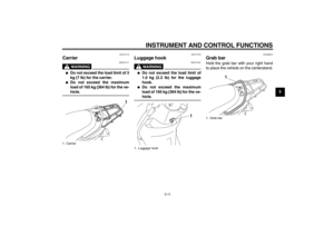
Carrier
WARNING
EWA10171
●
Do not exceed the load limit of 3
kg (7 lb) for the carrier.
●
Do not exceed the maximum
load of 165 kg (364 lb) for the ve-
hicle.
EAUT1072
Luggage hook
WARNING
EWAT1031
●
Do not exceed the load limit of
1.0 kg (2.2 lb) for the luggage
hook.
●
Do not exceed the maximum
load of 165 kg (364 lb) for the ve-
hicle.
EAU29910
Grab bar Hold the grab bar with your right hand
to place the vehicle on the centerstand.
1. Carrier
1
1. Luggage hook
1
1. Grab bar
1
U1RSE0E0.book Page 11 Tuesday, October 18, 2011 8:56 AM
Page 28 of 76

INSTRUMENT AND CONTROL FUNCTIONS
3-12
3
EAU15305
Sidestand The sidestand is located on the left side
of the frame. Raise the sidestand or
lower it with your foot while holding the
vehicle upright.TIPThe built-in sidestand switch is part of
the ignition circuit cut-off system, which
cuts the ignition in certain situations.
(See the following section for an expla-
nation of the ignition circuit cut-off sys-
tem.)
WARNING
EWA10241
The vehicle must not be ridden with
the sidestand down, or if the side-
stand cannot be properly moved up
(or does not stay up), otherwise the
sidestand could contact the ground
and distract the operator, resulting
in a possible loss of control.
Yamaha’s ignition circuit cut-off
system has been designed to assist
the operator in fulfilling the respon-
sibility of raising the sidestand be-
fore starting off. Therefore, check
this system regularly and have a
Yamaha dealer repair it if it does not
function properly.
EAU15373
Ignition circuit cut-off system The ignition circuit cut-off system (com-
prising the sidestand switch and brake
light switches) has the following func-
tions.●
It prevents starting when the side-
stand is up, but neither brake is ap-
plied.
●
It prevents starting when either
brake is applied, but the sidestand
is still down.
●
It cuts the running engine when the
sidestand is moved down.
Periodically check the operation of the
ignition circuit cut-off system according
to the following procedure.
TIPThis check is most reliable if performed
with a warmed-up engine.
1. Sidestand
1
U1RSE0E0.book Page 12 Tuesday, October 18, 2011 8:56 AM
Page 29 of 76

INSTRUMENT AND CONTROL FUNCTIONS
3-13
3
With the engine turned off:
1. Move the sidestand down.
2. Make sure that the engine stop switch is turned on.
3. Turn the key on.
4. Keep the front or rear brake applied.
5. Push the start switch.
Does the engine start?
With the engine still off:
6. Move the sidestand up.
7. Keep the front or rear brake applied.
8. Push the start switch.
Does the engine start?
With the engine still running:
9. Move the sidestand down.
Does the engine stall?
The system is OK. The scooter can be ridden.The sidestand switch may not be working correctly.
The scooter should not be ridden until
checked by a Yamaha dealer.
The sidestand switch may not be working correctly.
The scooter should not be ridden until
checked by a Yamaha dealer.
YES NO YES NO NO YES
The brake switch may not be working correctly.
The scooter should not be ridden until
checked by a Yamaha dealer.• The vehicle must be placed on the center-
stand during this inspection.• If a malfunction is noted, have a Yamaha
dealer check the system before riding.
WARNING
U1RSE0E0.book Page 13 Tuesday, October 18, 2011 8:56 AM
Page 30 of 76

FOR YOUR SAFETY – PRE-OPERATION CHECKS
4-1
4
EAU15596
Inspect your vehicle each time you use it to make sure the vehicle is in safe operating condition. Always follow the inspection
and maintenance procedures and schedules described in the Owner’s Manual.
WARNING
EWA11151
Failure to inspect or maintain the vehicle properly increases the possibility of an accident or equipment damage.
Do not operate the vehicle if you find any problem. If a problem cannot be corrected by the procedures provided in
this manual, have the vehicle inspected by a Yamaha dealer.Before using this vehicle, check the following points:
ITEM CHECKS PAGE
Fuel Check fuel level in fuel tank.
Refuel if necessary.
Check fuel line for leakage.3-6
Engine oil Check oil level in engine.
If necessary, add recommended oil to specified level.
Check vehicle for oil leakage.6-10
Final transmission oil Check vehicle for oil leakage. 6-12
Front brake Check operation.
If soft or spongy, have Yamaha dealer bleed hydraulic system.
Check brake pads for wear.
Replace if necessary.
Check fluid level in reservoir.
If necessary, add specified brake fluid to specified level.
Check hydraulic system for leakage.6-19, 6-20
Rear brake Check operation.
Lubricate cable if necessary.
Check lever free play.
Adjust if necessary.6-18, 6-19
U1RSE0E0.book Page 1 Tuesday, October 18, 2011 8:56 AM
Page 31 of 76

FOR YOUR SAFETY – PRE-OPERATION CHECKS
4-2
4
Throttle grip Make sure that operation is smooth.
Check throttle grip free play.
If necessary, have Yamaha dealer adjust throttle grip free play and lubricate cable
and grip housing.6-15, 6-21
Control cables Make sure that operation is smooth.
Lubricate if necessary.6-21
Wheels and tires Check for damage.
Check tire condition and tread depth.
Check air pressure.
Correct if necessary.6-16, 6-17
Brake levers Make sure that operation is smooth.
Lubricate lever pivoting points if necessary.6-22
Centerstand, sidestand Make sure that operation is smooth.
Lubricate pivots if necessary.6-22
Chassis fasteners Make sure that all nuts, bolts and screws are properly tightened.
Tighten if necessary.—
Instruments, lights, signals
and switches Check operation.
Correct if necessary.—
Sidestand switch Check operation of ignition circuit cut-off system.
If system is not working correctly, have Yamaha dealer check vehicle.3-12 ITEM CHECKS PAGE
U1RSE0E0.book Page 2 Tuesday, October 18, 2011 8:56 AM
Page 32 of 76

OPERATION AND IMPORTANT RIDING POINTS
5-1
5
EAU15951
Read the Owner’s Manual carefully to
become familiar with all controls. If
there is a control or function you do not
understand, ask your Yamaha dealer.
WARNING
EWA10271
Failure to familiarize yourself with
the controls can lead to loss of con-
trol, which could cause an accident
or injury.
EAUT1865
Starting the engine NOTICE
ECA10250
See page 5-3 for engine break-in in-
structions prior to operating the ve-
hicle for the first time.In order for the ignition circuit cut-off
system to enable starting, the side-
stand must be up.
See page 3-12 for more information.
1. Turn the key to “ON”.
The engine trouble warning light
should come on for a few seconds,
then go off. NOTICE: If the warn-
ing light does not go off, have a
Yamaha dealer check its electri-
cal circuit.
[ECAT1120]
2. Close the throttle completely.
3. Start the engine by pushing the
start switch while applying the front
or rear brake.
If the engine does not start, re-
lease the start switch, wait a few
seconds, and then try again. Each
starting attempt should be as short
as possible to preserve the bat-
tery. Do not crank the engine more
than 5 seconds on any one at-tempt. If the engine does not start
with the starter motor, try using the
kickstarter.
NOTICE
ECA11042
For maximum engine life, never ac-
celerate hard when the engine is
cold!
U1RSE0E0.book Page 1 Tuesday, October 18, 2011 8:56 AM


 for the front stor-
age compartment.
●
Do not exceed the maximum")
 for the carrier.
●
Do not exceed the maximum
load of 165 kg (364 lb) for th")