Page 41 of 76

PERIODIC MAINTENANCE AND ADJUSTMENT
6-6
6
EAU45610
TIP●
Air filter
This model’s air filter is equipped with a disposable oil-coated paper element, which must not be cleaned with com-
pressed air to avoid damaging it.
The air filter element needs to be replaced more frequently when riding in unusually wet or dusty areas.
●
V-belt case air filter
The air filter needs more frequent service if you are riding in unusually wet or dusty areas.
●
Hydraulic brake service
Regularly check and, if necessary, correct the brake fluid level.
Every two years replace the internal components of the brake master cylinder and caliper, and change the brake fluid.
Replace the brake hose every four years and if cracked or damaged.
21*Front and rear brake
switches Check operation.√√√√√√
22Moving parts and
cables Lubricate.√√√√√
23*Throttle grip Check operation.
Check throttle grip free play, and
adjust if necessary.
Lubricate cable and grip housing.√√√√√
24*Lights, signals and
switches Check operation.
Adjust headlight beam.√√√√√√ NO. ITEM CHECK OR MAINTENANCE JOBODOMETER READING
ANNUAL
CHECK 1000 km
(600 mi)6000 km
(3500 mi)12000 km
(7000 mi)18000 km
(10500 mi)24000 km
(14000 mi)
U1RSE0E0.book Page 6 Tuesday, October 18, 2011 8:56 AM
Page 42 of 76
PERIODIC MAINTENANCE AND ADJUSTMENT
6-7
6
EAU18712
Removing and installing cowl-
ings and panels The cowlings and panels shown need
to be removed to perform some of the
maintenance jobs described in this
chapter. Refer to this section each time
a cowling or panel needs to be re-
moved and installed.
EAU18853
Cowling A
To remove the cowlingRemove the screws, and then pull the
cowling off as shown.To install the cowling
Place the cowling in the original posi-
tion, and then install the screws.
EAU53290
Cowling B
To remove the cowling1. Remove the screws, and then pull
the cowling off as shown.
1. Cowling A
2. Cowling B
3. Panel A
4. Panel B
12
34
1. Screw
1. Cowling A
11
1
1. Screw
1. Screw
2. Cowling B
1
12
U1RSE0E0.book Page 7 Tuesday, October 18, 2011 8:56 AM
Page 43 of 76
PERIODIC MAINTENANCE AND ADJUSTMENT
6-8
6 2. Disconnect the headlight lead cou-
pler, and the auxiliary light lead
coupler.
To install the cowling
1. Connect the headlight lead cou-
pler, and the auxiliary light lead
coupler.
2. Place the cowling in the original
position, and then install the
screws.
EAU19281
Panel A
To remove the panelRemove the screw, and then pull the
panel off as shown.To install the panel
Place the panel in the original position,
and then install the screw.
EAU45450
Panel B
To remove the panel1. Pull up the floorboard mat.2. Remove the screws, and then pull
the panel off as shown.
To install the panel
1. Place the panel in the original posi-
tion, and then install the screws.
2. Place the floorboard mat in the
original position.
1. Headlight lead coupler
2. Auxiliary light lead coupler
1
2
1. Screw
1
1. Floorboard mat
1. Screw
1
1
U1RSE0E0.book Page 8 Tuesday, October 18, 2011 8:56 AM
Page 44 of 76

PERIODIC MAINTENANCE AND ADJUSTMENT
6-9
6
EAU45591
Checking the spark plug The spark plug is an important engine
component, which is easy to check.
Since heat and deposits will cause any
spark plug to slowly erode, the spark
plug should be removed and checked
in accordance with the periodic mainte-
nance and lubrication chart. In addition,
the condition of the spark plug can re-
veal the condition of the engine.
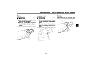
To remove the spark plug
1. Place the vehicle on the center-
stand.
2. Remove panel A. (See page 6-7.)
3. Remove the spark plug cap.
4. Remove the spark plug as shown,
using the spark plug wrench,
which is located in the rear storage
compartment. (See page 3-9.)
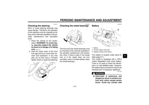
To check the spark plug
1. Check that the porcelain insulator
around the center electrode of the
spark plug is a medium-to-light tan
(the ideal color when the vehicle is
ridden normally).
TIPIf the spark plug shows a distinctly dif-
ferent color, the engine could be oper-
ating improperly. Do not attempt to
diagnose such problems yourself. In-
stead, have a Yamaha dealer check
the vehicle.2. Check the spark plug for electrode
erosion and excessive carbon or
other deposits, and replace it if
necessary.
3. Measure the spark plug gap with a
wire thickness gauge and, if nec-
essary, adjust the gap to specifica-
tion.
1. Spark plug wrench
1. Spark plug wrench
1
1
Specified spark plug:
NGK/CR6HSA
U1RSE0E0.book Page 9 Tuesday, October 18, 2011 8:56 AM
Page 45 of 76

PERIODIC MAINTENANCE AND ADJUSTMENT
6-10
6 To install the spark plug
1. Clean the surface of the spark plug
gasket and its mating surface, and
then wipe off any grime from the
spark plug threads.
2. Install the spark plug with the
spark plug wrench, and then tight-
en it to the specified torque.
TIPIf a torque wrench is not available when
installing a spark plug, a good estimate
of the correct torque is 1/4–1/2 turn
past finger tight. However, the spark
plug should be tightened to the speci-
fied torque as soon as possible.3. Install the spark plug cap.
4. Install the panel.
EAU53150
Engine oil The engine oil level should be checked
before each ride. In addition, the oil
must be changed at the intervals spec-
ified in the periodic maintenance and
lubrication chart.
To check the engine oil level
1. Place the vehicle on the center-
stand. A slight tilt to the side can
result in a false reading.
2. Start the engine, warm it up for
several minutes, and then turn it
off.
3. Wait a few minutes until the oil set-
tles, remove the engine oil filler
cap, wipe the engine oil dipstick
clean, insert it back into the oil filler
hole (without screwing it in), and
then remove it again to check the
oil level.TIPThe engine oil should be between the
minimum and maximum level marks.
1. Spark plug gapSpark plug gap:
0.6–0.7 mm (0.024–0.028 in)
Tightening torque:
Spark plug:
13 Nm (1.3 m·kgf, 9.4 ft·lbf)
U1RSE0E0.book Page 10 Tuesday, October 18, 2011 8:56 AM
Page 46 of 76

PERIODIC MAINTENANCE AND ADJUSTMENT
6-11
64. If the engine oil is at or below the
minimum level mark, add sufficient
oil of the recommended type to
raise it to the correct level.
5. Insert the engine oil dipstick into
the oil filler hole, and then tighten
the oil filler cap.
To change the engine oil
1. Place the vehicle on the center-
stand.
2. Start the engine, warm it up for
several minutes, and then turn it
off.3. Place an oil pan under the engine
to collect the used oil.
4. Remove the engine oil filler cap,
and then remove the engine oil
drain bolt and its gasket to drain
the oil from the crankcase.
5. Install the engine oil drain bolt and
its new gasket, and then tighten
the bolt to the specified torque.
6. Refill with the specified amount of
the recommended engine oil, and
then install and tighten the engine
oil filler cap.
NOTICE
ECA11670
●
Do not use oils with a diesel
specification of “CD” or oils of a
higher quality than specified. In
addition, do not use oils labeled
“ENERGY CONSERVING II” or
higher.
●
Be sure no foreign material en-
ters the crankcase.
7. Start the engine, and then let it idle
for several minutes while checking
it for oil leakage. If oil is leaking, im-
mediately turn the engine off and
check for the cause.
8. Turn the engine off, and then
check the oil level and correct it if
necessary.
1. Engine oil filler cap
2. Engine oil dipstick
3. Maximum level mark
4. Minimum level mark
32
1
4
1. Engine oil drain bolt
2. GasketTightening torque:
Engine oil drain bolt:
20 Nm (2.0 m·kgf, 14 ft·lbf)1
2
Recommended engine oil:
See page 8-1.
Oil quantity:
1.00 L (1.06 US qt, 0.88 Imp.qt)
U1RSE0E0.book Page 11 Tuesday, October 18, 2011 8:56 AM
Page 47 of 76

PERIODIC MAINTENANCE AND ADJUSTMENT
6-12
6
EAU20066
Final transmission oil The final transmission case must be
checked for oil leakage before each
ride. If any leakage is found, have a
Yamaha dealer check and repair the
scooter. In addition, the final transmis-
sion oil must be changed as follows at
the intervals specified in the periodic
maintenance and lubrication chart.
1. Start the engine, warm up the final
transmission oil by riding the
scooter for several minutes, and
then stop the engine.
2. Place the scooter on the center-
stand.
3. Place an oil pan under the final
transmission case to collect the
used oil.
4. Remove the final transmission oil
filler cap and its O-ring from the fi-
nal transmission case.5. Remove the final transmission oil
drain bolt and its gasket to drain
the oil from the final transmission
case.6. Install the final transmission oil
drain bolt and its new gasket, and
then tighten the bolt to the speci-
fied torque.
7. Refill with the specified amount of
the recommended final transmis-
sion oil. WARNING! Make sure
that no foreign material enters
the final transmission case.
Make sure that no oil gets on the
tire or wheel.
[EWA11311]
8. Install the final transmission oil fill-
er cap and its new O-ring, and then
tighten the oil filler cap.
9. Check the final transmission case
for oil leakage. If oil is leaking,
check for the cause.
1. Final transmission oil filler cap
2. O-ring
1. Final transmission oil drain bolt
2. Gasket
1
2
12
Tightening torque:
Final transmission oil drain bolt:
23 Nm (2.3 m·kgf, 17 ft·lbf)
Recommended final transmission
oil:
See page 8-1.
Oil quantity:
0.13 L (0.14 US qt, 0.11 Imp.qt)
U1RSE0E0.book Page 12 Tuesday, October 18, 2011 8:56 AM
Page 48 of 76

PERIODIC MAINTENANCE AND ADJUSTMENT
6-13
6
EAU53311
Air filter and V-belt case air fil-
ter elements The air filter element should be re-
placed and the V-belt case air filter ele-
ment should be cleaned at the intervals
specified in the periodic maintenance
and lubrication chart. Service the air fil-
ter elements more frequently if you are
riding in unusually wet or dusty areas.
The air filter check hose must be fre-
quently checked and cleaned if neces-
sary.
Replacing the air filter element
1. Place the scooter on the center-
stand.
2. Remove the air filter case cover by
removing the screws.3. Pull the air filter element out.
4. Insert a new air filter element into
the air filter case. NOTICE: Make
sure that the air filter element is
properly seated in the air filter
case. The engine should neverbe operated without the air filter
element installed, otherwise the
piston(s) and/or cylinder(s) may
become excessively worn.
[ECA10481]
5. Install the air filter case cover by in-
stalling the screws.
Cleaning the air filter check hose
1. Check the hose on the rear side of
the air filter case for accumulated
dirt or water.
2. If dirt or water is visible, remove
the hose from the clamp, clean it,
and then install it.
1. Air filter case cover
2. Screw
1. Air filter element
1
2
2
1
1. Air filter check hose
2. Clamp
12
U1RSE0E0.book Page 13 Tuesday, October 18, 2011 8:56 AM