2012 VOLKSWAGEN TRANSPORTER tow
[x] Cancel search: towPage 163 of 486
Emptying the removable ashtray
• Lift the removable ashtray out of the drink hold-er.
• Open the removable ashtray and empty the cooled ashes into a suitable waste container.
• Once it has been emptied, place the removable ashtray back into the drink holder from above.
r-1'11 First read and observe the introductory L-J.::.IJ information and safety warnings & on page 161.
Depending on the vehicle equipment, a cigarette lighter may be fitted in the drink holder or in the stowage compartment in the dash panel.
• With the ignition switched on, press in the knob on the cigarette lighter.
• Wait for the lighter to pop out.
• Pull out the cigarette lighter and light the tobac-co product on the glowing
• Insert the cigarette lighter back into the socket.
Electrical sockets
c:r:n Introduction
This chapter contains information on the following subjects:
Sockets in the vehicle .......... . 164
Electrical equipment can be connected to the sock-ets in the vehicle.
The connected devices must be in good condition. Do not use faulty devices.
Additional information and warnings:
• Cigarette lighter 161
• Accessories, modifications, repairs and renewal of parts 394
• Consumer information 404
A WARNING
Improper use of the sockets and electrical ac-cessories can cause fires and severe injuries.
A WARNING
Improper use of the cigarette lighter can cause fires, burns and other serious injuries.
• Always use the cigarette lighter properly, and only use it to light tobacco products.
• Never leave children in the vehicle unat-tended. The cigarette lighter can be used when the ignition is switched on.
m The cigarette lighter can also be used as a L!..J 12-volt socket 163.
• Never leave children in the vehicle unat-tended. Sockets and the devices connected to them can be used when the ignition is switched on.
• If the electrical device gets too hot, switch off the device immediately and disconnect it from the socket.
CD
• In order to prevent damage to the electrical system, never connect equipment that gener-ates electricity, such as solar panels or battery chargers for charging the vehicle battery, to the 12-voit socket.
• Only use accessories that have been ap-proved in accordance with current guidelines concerning electromagnetic compatibility. .,..
Practical equipment 163
Page 164 of 486
CD
• In order to avoid damage due to voltage fluctuation, always switch any electrical con-sumers connected to the 12-volt sockets off be-fore switching the ignition or the engine on or off. When the start/stop system automatically switches off and restarts the engine, it Is not necessary to switch off any connected electri-cal consumers.
• Never connect electrical devices requiring more electrical power to a 12-volt socket. The vehicle's electrical system can be damaged If the maximum power output Is exceeded.
• Never feed electricity Into the socket.
Sockets in the vehicle
rT'n First read and observe the Introductory L-lo:J.I information and safety warnings&. on page 163.
There are two separate power circuits in the vehi-cle depending on the equipment:
• 12-volt DC circuit
• 230-volt AC circuit
Maximum power rating
Electrical Maximum power rating socket
12-volt 120 watts
230-volt 2500 watts
Do not exceed the maximum power rating. This al-so applies to the total power consumption of all connected devices if you connect several devices at the same time Introduction on page 163. The power rating of each device is stated on its type plate.
12-volt socket
Electrical equipment can be connected to the 12-volt sockets in the vehicle.
Using electrical appliances with the engine switch-ed off and the ignition switched on will drain the battery. Electrical consumers should therefore only be plugged into the sockets when the engine is running.
To prevent damage due to voltage fluctuation, switch off any connected devices before switching the ignition or engine on or off.
In the vehicle, there are 12-volt sockets in the fol-lowing locations, among others:
164 I Before the journey
Do not leave the engine running when the ve-l?1S hicle is stationary.
m Using electrical appliances with the engine L!..J switched off and the ignition switched on will drain the battery.
m Unshielded devices can cause interference L!..J with radio reception and vehicle electronics.
m Functional problems may occur with some L!..J devices when they are connected to the 230-volt socket due to the lower power output (wat-tage).
• In the stowage compartment on the dash panel under a small cover.
• In the stowage compartment in the dash panel.
• In the side trim panels in the passenger com-partment
• In the luggage compartment.
• In the roof frame of the pop-up roof.
230-volt grounded safety socket
The 230-volt grounded safety socket is supplied via electrical feed from the external socket 192.
The following electrical consumers are supplied from the 230-volt power supply via the external socket:
• Battery charger
• Depending on the vehicle equipment, the 230-volt grounded safety socket is located in the side trim panel behind the left front seat or on the side of the kitchen unit 192.
230-volt Euro socket
The 230-volt Euro socket is supplied via additional batteries or via an inverter and is located in the side trim panel behind the left front seat 192.
A DANGER !
High voltage In the electrical system!
• Never pour any liquid over the socket.
• Do not Insert any Items which will conduct electricity, such as knitting needles, Into the contacts of the 230-volt socket. .,.
Page 165 of 486

A DANGER (Continued)
• 230-volt socket with inverter switch:
CD
-Do not plug adapters or extension ca-bles into the 230-volt socket. Otherwise the built-in child lock will disengage and power will be supplied to the socket.
• Observe the operating instructions for any device that you plug into the socket.
• Never exceed the maximum power rating as this could damage the whole vehicle electrical system.
• Only use accessories that have been ap-proved in accordance with valid guidelines concerning electromagnetic compatibility.
CD
• Never feed electricity Into the socket.
• Do not plug any heavy devices or connec-tions, such as mains adapters, directly Into the socket.
• Only connect devices to the socket with a voltage that matches the voltage of the socket.
• 230-volt socket with inverter switch:
-Do not connect any lights which use neon tubes.
-With electrical devices that require a high level of current In the start phase, the built-In excess current switch will prevent the de-vice from being switched on. If this hap-pens, disconnect the device from the power supply and reconnect after waiting approxi-mately 10 seconds.
m Unshielded devices can cause interference W with radio reception and vehicle electronics.
[Q) Introduction
This chapter contains information on the following subjects:
Components ......... .
Folding the LCD screen out and in
DVD player ..
Controls on the LCD screen ...
Remote control ..
Settings on the LCD screen Settings on the DVD player
Care and protection
166
167 167
168
169
170 171
Use a suitable screen cleaner for cleaning the screen Be careful not to scratch the screen when cleaning it.
A WARNING
Improper use of the rear seat entertainment system could cause short-circuits, fire and serious Injuries.
• Protect the rear seat entertainment system against moisture and damp.
A WARNING
Objects that are loosely placed in the vehicle or not properly secured could be flung through the interior and cause injuries during a sudden driving or braking manoeuvre, or in the event of an accident.
• Always stow the remote control units and headsets securely In the stowage compart-ments.
A WARNING
Accidents and Injuries can occur If the driver Is distracted.
• Never allow use of the rear seat entertain-ment system to distract you from what Is happening on the road.
• Comply with legal regulations .
• Select volume settings that allow signals from outside the vehicle (such as emergency services sirens) to be easily heard at all times.
Practical equipment 165
Page 167 of 486

Folding the LCD screen out and in
Fig. 131 In the headliner: folding the LCD screen out
r-111 First read and observe the introductory L-b.U information and safety warnings & on page 165.
DVD player
r-111 First read and observe the introductory L-b.U information and safety warnings & on page 165.
Keep liquids away from the DVD player & in In-troduction on page 165. If you spill liquid on the DVD player, switch it off immediately and consult a Volkswagen Commercial Vehicles dealership.
High humidity can cause condensation in the DVD player and damage the reading head.
Do not place a DVD or CD in the DVD player if condensation has formed in it. Instead, switch the DVD player on and allow it to dry for around an hour.
To ensure excellent, high-quality CD or DVD repro-duction, only use COs or DVDs that are clean and undamaged.
Please do not stick any labels onto the DVDs or COs.
Always stow unused DVDs or COs securely in the vehicle.
Never expose DVDs or COs to direct sunlight.
Inserting a CD or DVD
• Push the CD or DVD into the slot at the side with the printed side facing upwards until the disc is pulled in automatically
Folding the LCD screen out
• Before folding out. make sure that there is enough space to do so.
• Press the button 131 G) and carefully fold the LCD screen downwards by hand as far as the in Introduction on page 166.
Folding the LCD screen in
• Carefully fold the LCD screen upwards until it clicks into in Introduction on page 166.
CD
Inserting or removing COs or DVDs incorrectly can damage the DVD player.
• Insert or remove the CD or DVD into or out of the slot at right angles to the side of the player, making sure that the CD or DVD does not become jammed in the slot.
• "Special shape COs" may not be inserted. They can damage the player.
• Do not insert COs or DVDs with adhesive la-bels on them Into the DVD player. The label could become detached from the CD or DVD and damage the drive mechanism.
m The DVD player may be unable to play cer-L!J tain COs, DVDs and file formats. For more in-formation on compatible COs, DVDs and file for-mats, contact a Volkswagen Commercial Vehicles dealership.
Page 172 of 486
• Press the [ENTER! button to confirm your selec-tion.
• Press the [SETUP! button again to leave the main menu.
The following settings can be made in the subme-nus:
• Picture format.
• Camera perspective.
• Language.
• Subtitles.
• Screen saver.
• Saving the last item played.
Tachograph
o::D Introduction
This chapter contains information on the following subjects:
Notes on the tachograph . . . . . . . . . . . . . . . . . 172
The function and operation of the factory-fitted ta-chograph can be found in an additional operating manual delivered with the vehicle.
If you retro-fit a tachograph to the vehicle, ensure it complies with relevant legislation.
Additional information and warnings:
• Towing a trailer 139
• Accessories. modifications, repairs and renewal of parts 394
Notes on the tachograph
I""'""'J'n First read and observe the Introductory L-lo:.l.l Information given on page 172.
Location
Depending on the model, the factory-fitted tacho-graph could be located in the middle of the dash panel or in a console on the dash panel.
Time
For the time settings, refer to the additional operat-ing instructions for the tachograph.
Please note that in digital tachographs, the time must be displayed in local time. The time on the printouts is always given in UTC (Coordinated Uni-versal Time).
1721 Before the journey
• Various audio settings.
• Colour system.
• Playback control for video COs
• Parental lock 172.
• Reset to default settings.
• Password protection.
Childproof locks
This function is only available in the case of DVDs with restricted access for young people and chil-dren. This menu is used to specify whether a DVD with access restrictions is to be played or whether a password has to be entered first.
m Manipulation of the tachograph and its signal, l.!J and misuse of the tachograph discs can re-sult in prosecution.
The digital tachograph has a buffer battery to pre-vent data loss. The buffer battery can supply power for approx. one year without an external power supply. This function is used if, for example, the digital tachograph is removed from the vehicle and stored or if left in a vehicle with a battery fault or a flat battery.
Legal requirements
By law. the tachograph must be used in:
Page 174 of 486
.--m First read and observe the introductory information given on page 173.
Switching on and off
• Turn the volume control on the powered radio or radio/navigation system Radio, provi-sion for mobile telephone, infotainment system, navigation system.
• Tap the function button with the digital voice en-hancement icon 135 CD in the top right cor-ner of the screen to open the menu for "setting the volume" directly.
• To switch off the digital voice enhancement se-lect the ICC menu item (In Car Communication) 136, and set the volume slider to the left-most position.
• To switch on the digital voice enhancement set the slide control from the leftmost position towards right to the desired volume.
• This setting is retained even after the ignition has been switched off and on.
174 I Before tho journey
Setting the volume
• Turn the volume control on the powered radio or radio/navigation system Radio, provi-sion for mobile telephone, infotainment system, navigation system.
• Tap the function button with the digital voice en-hancement icon 135 CD in the top right cor-ner of the screen to open the menu for "setting the volume" directly.
• Select the ICC menu item (In Car Communica-tion) 136, and set the slide control to the de-sired volume.
• This setting is retained even after the ignition has been switched off and on.
Page 175 of 486
Equipment, Multivan
Darkening the interior of the vehicle, Multivan
n:n Introduction
This chapter contains information on the following subjects:
Components of the opaque shades kit . . . 175
Assembling opaque shades for the windscreen and the rear window . . . . . . . 176
Fitting opaque shades for the windscreen and the rear window . . . . . . . . . . . . . . . . . . . . . . . . . 177
Fitting the opaque shades to the side windows . . . . . . . . . . . . . . . . . . . . . . . . . . . . . 178
Removing and stowing the opaque shades . . 179
Darkening the interior of the vehicle
The opaque shades kit is supplied in a zippered storage bag, which can be securely stowed in a drawer underneath the 3-seat bench.
Additional information and warnings:
• Windows 36
• Seat functions, front 61
Components of the opaque shades kit
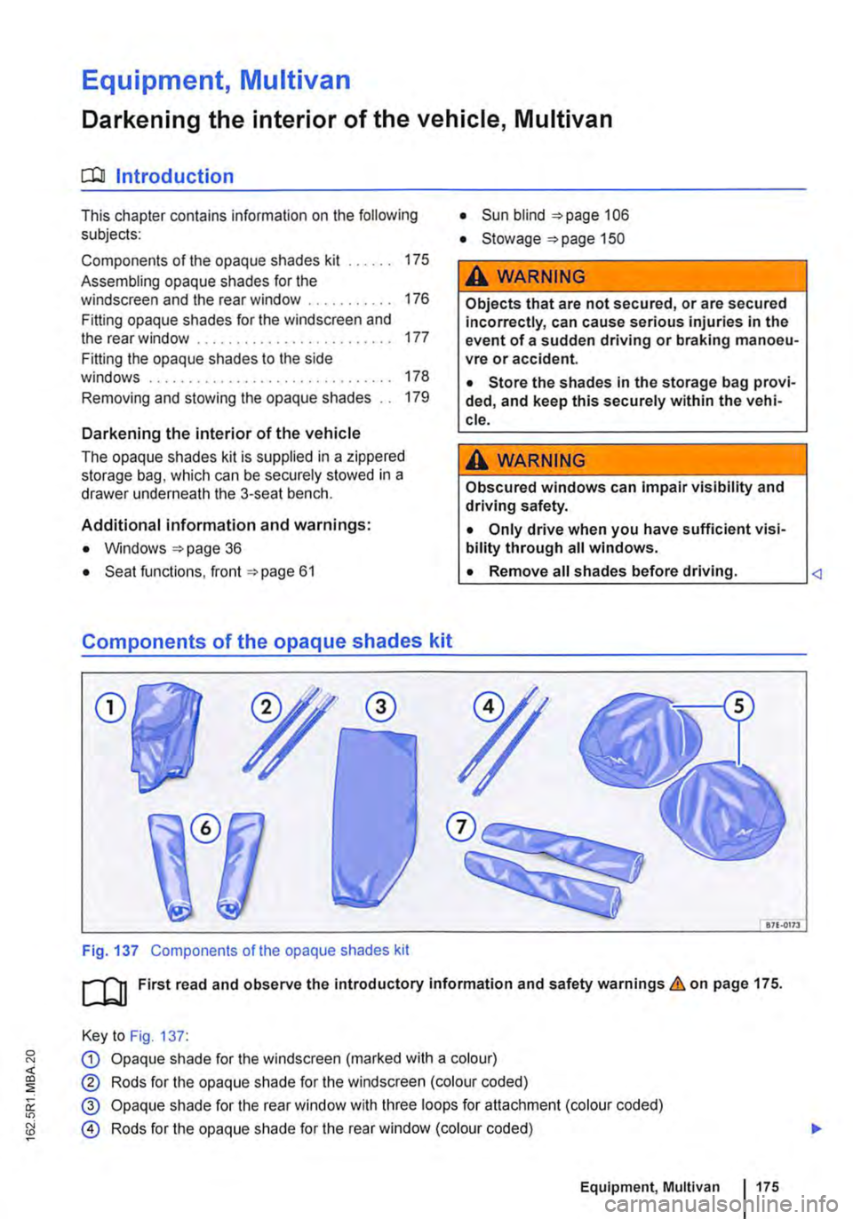
CD
Fig. 137 Components of the opaque shades kit
• Sun blind 106
• Stowage "'page 150
A WARNING
Objects that are not secured, or are secured incorrectly, can cause serious injuries in the event of a sudden driving or braking manoeu-vre or accident.
• Store the shades in the storage bag provi-ded, and keep this securely within the vehi-cle.
A WARNING
Obscured windows can impair visibility and driving safety.
• Only drive when you have sufficient visi-bility through all windows.
L• ___
&71.0173
[QJ First read and observe the introductory information and safety warnings.&. on page 175.
Key to Fig. 137:
G) Opaque shade for the windscreen (marked with a colour)
® Rods for the opaque shade for the windscreen (colour coded)
@ Opaque shade for the rear window with three loops for attachment (colour coded)
@ Rods for the opaque shade for the rear window (colour coded)
Equipment, Multivan 1175
Page 179 of 486
Removing and stowing the opaque shades
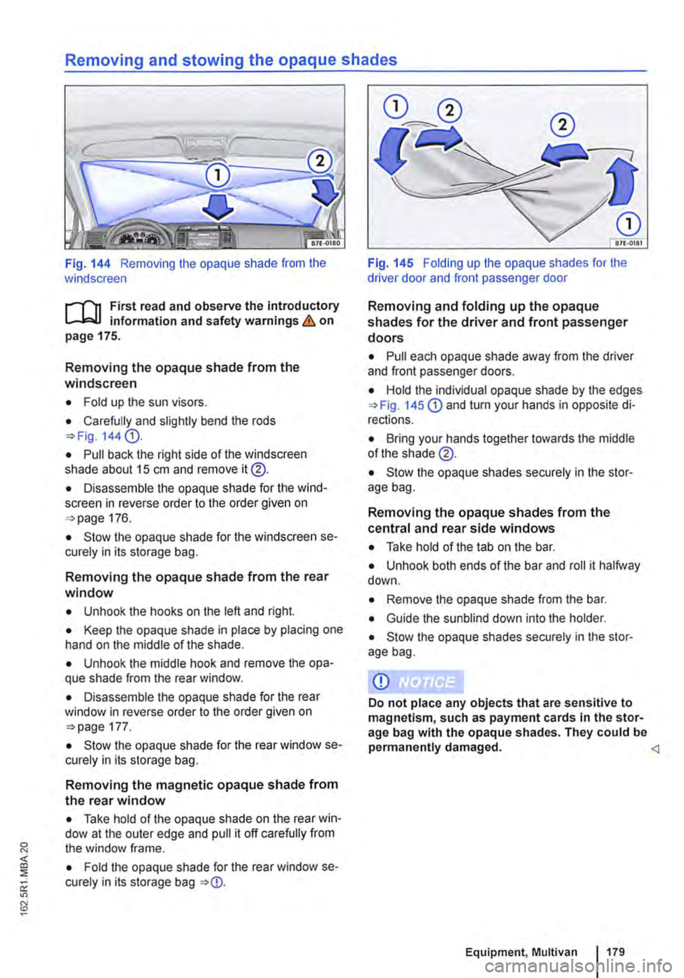
Fig. 144 Removing the opaque shade from the windscreen
,....-("n First read and observe the introductory L-.lc.l.l information and safety warnings & on page 175.
Removing the opaque shade from the windscreen
• Fold up the sun visors.
• Carefully and slightly bend the rods =>Fig. 144 G).
• Pull back the right side of the windscreen shade about 15 cm and remove it@.
• Disassemble the opaque shade for the wind-screen in reverse order to the order given on =>page 176.
• Stow the opaque shade for the windscreen se-curely in its storage bag.
Removing the opaque shade from the rear window
• Unhook the hooks on the left and right.
• Keep the opaque shade in place by placing one hand on the middle of the shade.
• Unhook the middle hook and remove the opa-que shade from the rear window.
• Disassemble the opaque shade for the rear window in reverse order to the order given on =>page 177.
• Stow the opaque shade for the rear window se-curely in its storage bag.
Removing the magnetic opaque shade from the rear window
• Take hold of the opaque shade on the rear win-dow at the outer edge and pull it off carefully from the window frame.
• Fold the opaque shade for the rear window se-curely in its storage bag =>CD.
Fig. 145 Folding up the opaque shades for the driver door and front passenger door
Removing and folding up the opaque shades for the driver and front passenger doors
• Pull each opaque shade away from the driver and front passenger doors.
• Hold the individual opaque shade by the edges =>Fig. 145 CD and turn your hands in opposite di-rections.
• Bring your hands together towards the middle of the shade @.
• Stow the opaque shades securely in the stor-age bag.
Removing the opaque shades from the central and rear side windows
• Take hold of the tab on the bar.
• Unhook both ends of the bar and roll it halfway down.
• Remove the opaque shade from the bar.
• Guide the sun blind down into the holder.
• Stow the opaque shades securely in the stor-age bag.
Equipment, Multivan 179