2012 SUBARU OUTBACK towing
[x] Cancel search: towingPage 13 of 474

10
Illustrated index &Exterior1) Engine hood lock release (page 11-7)
2) Headlight switch (page 3-27)
3) Bulb replacement (page 11-45)
4) Wiper switch (page 3-32)
5) Moonroof (page 2-27)
6) Roof rail (page 8-14)
7) Door locks (page 2-4)
8) Tire pressure (page 11-32)
9) Flat tires (page 9-6)
10) Fog light switch (page 3-30)
11) Tie-down hooks (page 9-14)
12) Towing hook (page 9-13)
Page 14 of 474
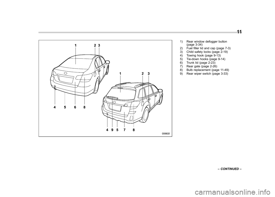
1) Rear window defogger button(page 3-34)
2) Fuel filler lid and cap (page 7-3)
3) Child safety locks (page 2-19)
4) Towing hook (page 9-13)
5) Tie-down hooks (page 9-14)
6) Trunk lid (page 2-23)
7) Rear gate (page 2-26)
8) Bulb replacement (page 11-49)
9) Rear wiper switch (page 3-33) 11
– CONTINUED –
Page 131 of 474

3-12Instruments and controls
indicators illuminates depending on the
status of the front passenger ’s SRS frontal
airbag determined by the SUBARU ad-
vanced frontal airbag system monitoring.
If the front passenger ’s SRS frontal airbag
is activated, the passenger ’s frontal airbag
ON indicator will illuminate while the OFF
indicator will remain off.
If the front passenger ’s SRS frontal airbag
is deactivated, the passenger ’s frontal
airbag ON indicator will remain off while
the OFF indicator will illuminate.
With the ignition switch turned to the “ON ”
position, if both the ON and OFF indica-
tors remain illuminated or off simulta-
neously even after the system check
period, the system is malfunctioning.
Contact your SUBARU dealer immedi-
ately for an inspection.
& CHECK ENGINE warn-
ing light/Malfunction
indicator light
CAUTION
If the CHECK ENGINE warning light/
malfunction indicator light illumi-
nates while you are driving, have
your vehicle checked/repaired by
your SUBARU dealer as soon as
possible. Continued vehicle opera- tion without having the emission
control system checked and re-
paired as necessary could cause
serious damage, which may not be
covered by your vehicle
’s warranty.
If this light illuminates steadily or blinks
while the engine is running, it may indicate
that there is a problem or potential
problem somewhere in the emission con-
trol system. ! If the light illuminates constantly
If the light illuminates constantly while
driving or does not turn off after the engine
starts, an emission control system mal-
function has been detected.
You should have your vehicle checked by
an authorized SUBARU dealer immedi-
ately.
NOTE
This light also illuminates when the fuel
filler cap is not tightened until it clicks.
If you have recently refueled your vehicle,
the cause of the CHECK ENGINE warning
light/malfunction indicator light coming on
could be a loose or missing fuel filler cap.
Remove the cap and retighten it until it
clicks. Make sure nothing is interfering
with the sealing of the cap. Tightening the
cap will not make the CHECK ENGINE warning light/malfunction indicator light
turn off immediately. It may take several
driving trips. If the light does not turn off,
take your vehicle to your authorized
SUBARU dealer immediately. !
If the light is blinking
If the light is blinking while driving, an
engine misfire condition has been de-
tected which may damage the emission
control system.
To prevent serious damage to the emis-
sion control system, you should conform
to the following instructions. . Reduce vehicle speed.
. Avoid hard acceleration.
. Avoid steep uphill grades.
. Reduce the amount of cargo, if possi-
ble.. Stop towing a trailer as soon as
possible.
The CHECK ENGINE warning light/mal-
function indicator light may stop blinking
and illuminate steadily after several driv-
ing trips. You should have your vehicle
checked by an authorized SUBARU deal-
er immediately.
Page 295 of 474

7-18Starting and operating
than 5 seconds in any position
except the “N ” or “P ” position
when the brake is applied or
when chocks are used in the
wheels. This may cause the
transmission fluid to overheat.
. Avoid shifting from one of the
forward driving positions into the“ R ” position or vice versa until
the vehicle has completely
stopped. Such shifting may
cause damage to the transmis-sion.
. When parking the vehicle, first
securely apply the parking brake
and then place the select lever inthe “P ” position. Avoid parking
for a long time with the select
lever in any other position as
doing so could result in a dead
battery.
NOTE . For AT models, when the engine
coolant temperature is still low, the
transmission will upshift to higher
engine speeds than when the coolant
temperature is sufficiently high in order
to shorten the warm-up time and
improve driveability. The gearshift tim-
ing will automatically shift to the nor- mal timing after the engine has warmedup..
Immediately after transmission fluid
is replaced, you may feel that the
transmission operation is somewhat
unusual. This results from invalidation
of data which the on-board computer
has collected and stored in memory to
allow the transmission to shift at the
most appropriate times for the current
condition of your vehicle. Optimized
shifting will be restored as the vehicle
continues to be driven for a while.. When driving a vehicle that is
equipped with CVT under continuous
heavy load conditions such as towing a
camper or climbing a long, steep hill,
the engine speed or the vehicle speed
may automatically be reduced. This is
not a malfunction. This phenomenon
results from the engine control func-
tion maintaining the cooling perfor-
mance of the vehicle. The engine and
vehicle speed will return to a normal
speed when the engine is able to
maintain the optimum cooling perfor-
mance after the heavy load decreases.
Driving under a heavy load must be
performed with extreme care. Do not
try to pass a vehicle in front when
driving on an uphill slope while towing.. The continuously variable transmis-
sion is a chain type system that provides superior transmission effi-
ciency for maximum fuel economy. At
times, depending on varying driving
conditions, a chain operating sound
may be heard that is characteristic of
this type of system.
& Select lever
: With the brake pedal depressed, shift
while pressing the button in
: Shift while pressing the button in: Shift without pressing the button
The select lever has four positions, “P ”,
“ R ”, “N ”, “D ”and also has a manual gate
for using the manual mode. ! P (Park)
This position is for parking the vehicle and
starting the engine.
Page 304 of 474
that full vehicle control will be
maintained at all times and under
all conditions, its activation
should be seen as a sign that
the speed of the vehicle should
be reduced considerably.
. Whenever suspension compo-
nents, steering components, or
an axle are removed from a
vehicle equipped with the Vehicle
Dynamics Control system, have
an inspection of that system
performedbyanauthorized
SUBARU dealer.
. The following precautions should
be observed in order to ensure
that the Vehicle Dynamics Con-
trol system is operating properly. – All four wheels should be
fitted with tires of the same
size, type, and brand. Further-
more, the amount of wear
should be the same for all
four tires.
– Keep the tire pressure at the
proper level as shown on the
vehicle placard attached to
the driver ’s side door pillar.
– Use only the specified tem-
porary spare tire to replace a
flat tire. With a temporary spare tire, the effectiveness of
the Vehicle Dynamics Control
system is reduced and this
should be taken into account
when driving the vehicle in
such a condition.
. If non-matching tires are used,
the Vehicle Dynamics Control
system may not operate cor-
rectly.
In the event of wheelspin and/or skidding
on a slippery road surface and/or during
cornering and/or an evasive maneuver,
the Vehicle Dynamics Control system
adjusts the engine ’s output and the
wheels ’respective braking forces to help
maintain traction and directional control. . Traction Control Function
The traction control function is designed to
prevent spinning of the driving wheels on
slippery road surfaces, thereby helping to
maintain traction and directional control.
Activation of this function is indicated by
flashing of the Vehicle Dynamics Control
operation indicator light. . Skid Suppression Function
The skid suppression function is designed
to help maintain directional stability by
suppressing the wheels ’tendency to slide
sideways during steering operations. Acti- vation of this function is indicated by
flashing of the Vehicle Dynamics Control
operation indicator light.
NOTE . The Vehicle Dynamics Control sys-
tem may be considered normal when
the following conditions occur.
–Slight twitching of the brake
pedal is felt. – The vehicle or steering wheel
shakes to a small degree.– An operating sound from the
engine compartment is heard
briefly when starting the engine
and when driving off after starting
the engine. – The brake pedal seems to jolt
when driving off after starting the engine.
. In the following circumstances, the
vehicle may be less stable than it feels
to the driver. The Vehicle Dynamics
Control System may therefore operate.
Such operation does not indicate a
system malfunction.
–on gravel-covered or rutted
roads – on unfinished roads
– when the vehicle is towing a
trailer– when the vehicle is fitted with Starting and operating
7-27
– CONTINUED –
Page 310 of 474
the brake system warning light has
illuminated. Otherwise, the Hill
Holder function may not operate
properly and an accident may occur.
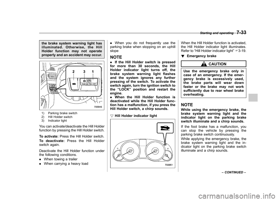
1) Parking brake switch
2) Hill Holder switch
3) Indicator light
You can activate/deactivate the Hill Holder
function by pressing the Hill Holder switch.
To activate: Press the Hill Holder switch.
To deactivate: Press the Hill Holder
switch again.
Deactivate the Hill Holder function under
the following conditions. . When towing a trailer
. When carrying a heavy load .
When you do not frequently use the
parking brake when stopping on an uphill slope NOTE . If the Hill Holder switch is pressed
for more than 30 seconds, the Hill
Holder indicator light turns off, the
brake system warning light flashes
and the system ignores any further
pressing of the switch. To activate the
switch again, turn the ignition switch tothe “LOCK ”position and restart the
engine.. When the Hill Holder function is
deactivated while the Hill Holder func-
tion has a malfunction, if you press the
Hill Holder switch, a chirp sounds. ! Hill Holder indicator light
When the Hill Holder function is activated,
the Hill Holder indicator light illuminates.
Refer to “Hill Holder indicator light ”F 3-19.
! Emergency brake
CAUTION
Use the emergency brake only in
case of an emergency. If the emer-
gency brake is excessively used,
the brake parts will wear down
faster or the brake may not work
sufficiently due to rear wheel brakeoverheating.
NOTE
While using the emergency brake, the
brake system warning light and the
indicator light on the parking brake
switch illuminate and a chirp sounds.
If the foot brake has a malfunction, you
canstopthevehiclebypressingthe
parking brake switch continuously.
While applying the emergency brake, the
brake system warning light and the in-
dicator light on the parking brake switch
illuminate and a chirp sounds. Starting and operating
7-33
– CONTINUED –
Page 312 of 474
Cruise control
Cruise control enables you to maintain a
constant vehicle speed without holding
your foot on the accelerator pedal and it is
operative when the vehicle speed is 25
mph (40 km/h) or more.
WARNING
Do not use the cruise control under
any of the following conditions.
These may cause loss of vehiclecontrol. . driving up or down a steep grade
. driving on slippery or winding
roads
. driving in heavy traffic
. towing a trailer
NOTE . If you press the “CRUISE ”main
switch button while turning the ignition switch “ON ”, the cruise control func-
tion is deactivated and the cruise
control indicator light flashes. To re-
activate the cruise control function,
turn the ignition switch back to the“ Acc ”or “LOCK ”position, and then
turn it again to the “ON ”position.
. Make sure the “CRUISE ”main switch is turned off when the cruise
control is not in use to avoid uninten-
tionally setting of the cruise control. &
To set cruise control
1. Press the “CRUISE ”main switch
button.
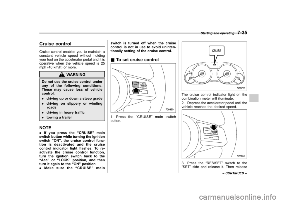
The cruise control indicator light on the
combination meter will illuminate.
2. Depress the accelerator pedal until the
vehicle reaches the desired speed.
3. Press the “RES/SET ”switch to the
“ SET ”side and release it. Then release Starting and operating
7-35
– CONTINUED –
Page 316 of 474
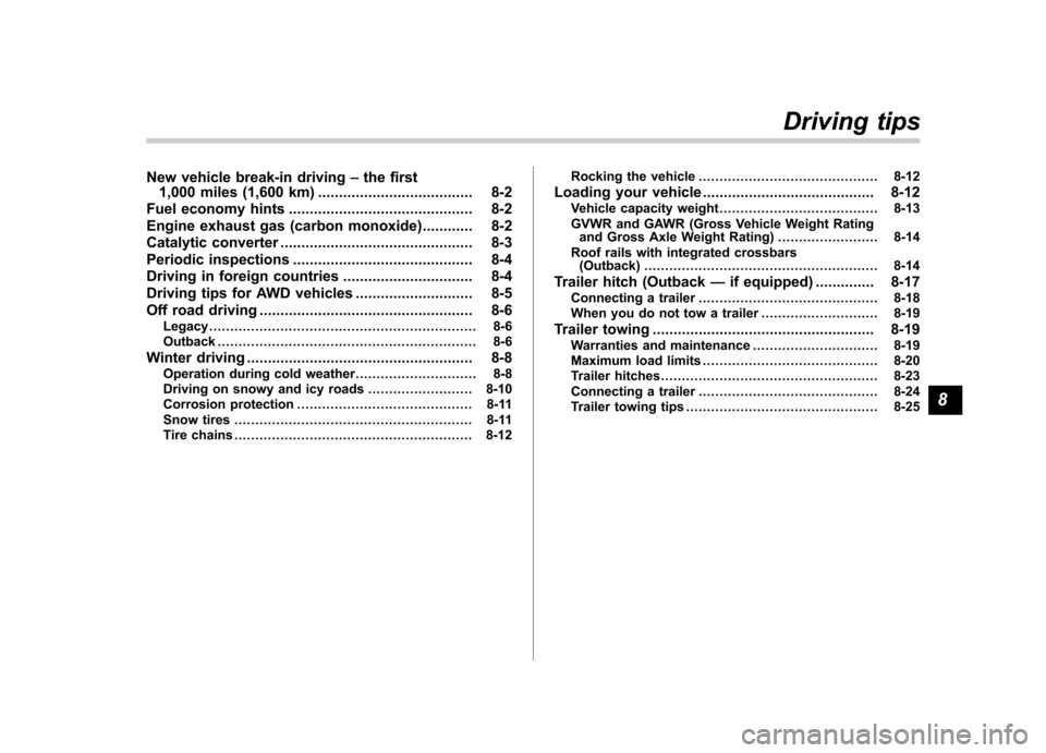
New vehicle break-in driving–the first
1,000 miles (1,600 km) ..................................... 8-2
Fuel economy hints ............................................ 8-2
Engine exhaust gas (carbon monoxide) ............ 8-2
Catalytic converter .............................................. 8-3
Periodic inspections ........................................... 8-4
Driving in foreign countries ............................... 8-4
Driving tips for AWD vehicles ............................ 8-5
Off road driving ................................................... 8-6
Legacy ................................................................ 8-6
Outback .............................................................. 8-6
Winter driving ...................................................... 8-8
Operation during cold weather ............................. 8-8
Driving on snowy and icy roads ......................... 8-10
Corrosion protection .......................................... 8-11
Snow tires ......................................................... 8-11
Tire chains ......................................................... 8-12 Rocking the vehicle
........................................... 8-12
Loading your vehicle ......................................... 8-12
Vehicle capacity weight ...................................... 8-13
GVWR and GAWR (Gross Vehicle Weight Rating and Gross Axle Weight Rating) ........................ 8-14
Roof rails with integrated crossbars (Outback) ........................................................ 8-14
Trailer hitch (Outback —if equipped) .............. 8-17
Connecting a trailer ........................................... 8-18
When you do not tow a trailer .. .......................... 8-19
Trailer towing ..................................................... 8-19
Warranties and maintenance .............................. 8-19
Maximum load limits .......................................... 8-20
Trailer hitches .................................................... 8-23
Connecting a trailer ........................................... 8-24
Trailer towing tips .............................................. 8-25Driving tips
8