2012 SUBARU OUTBACK engine warning light
[x] Cancel search: engine warning lightPage 22 of 474

&Warning and indicator lights
Mark Name Page
Seatbelt warning light 3-9
Front passenger ’s
seatbelt warning light 3-9
SRS airbag system
warning light3-11
CHECK ENGINE warn-
ing light/Malfunction in-
dicator light3-12
Coolant temperature
low indicator light/Cool-
ant temperature high
warning light3-13
Charge warning light 3-14
Oil pressure warning light
3-14
Engine oil level warning light3-14
AT OIL TEMP warning
light (AT and CVT mod- els)3-14
/ABS warning light 3-16 Mark Name Page
/Brake system warning light
3-17
Hill Holder indicator light3-19
Door open indicator light
3-19
Low fuel warning light 3-19
All-Wheel Drive warn-
ing light (AT and CVT models)3-20
Vehicle Dynamics Con-
trol warning light/Vehi-
cle Dynamics Control
operation indicator light3-20
Vehicle Dynamics Con-
trol OFF indicator light
3-21
Security indicator light 3-21
Turn signal indicator lights
3-22
High beam indicator light3-22
Front fog light indicator
light (if equipped)3-23Mark Name Page
Cruise control indicator light
3-23
Cruise control set indi-
cator light3-23
Headlight indicator light 3-23
Low tire pressure
warning light
(U.S. spec. models)3-15
/Front passenger
’s fron-
tal airbag ON indicator light 3-11
/Front passenger
’s fron-
tal airbag OFF indicator light 3-11
Shift-up indicator 3-22
Windshield washer fluid
warning light
3-1919
Page 30 of 474

The seat heater operates when the igni-
tion switch is either in the“Acc ”or “ON ”
position.
To turn on the seat heater, press the “ LOW ”or “HIGH ”position on the switch,
as desired, depending on the tempera-ture.
Selecting the “HIGH ”position will cause
the seat to heat up quicker.
To turn off the seat heater, slightly press
the opposite side of the current position.
The indicator located on the switch illumi-
nates when the seat heater is in operation.
When the vehicle ’s interior is warmed
enough or before you leave the vehicle,
be sure to turn the switch off.
CAUTION
. There is a possibility that people
with delicate skin may suffer
slight burns even at low tempera-
tures if they use the seat heater
for a long period of time. When
using the heater, always be sure
to warn the persons concerned. .
Do not put anything on the seat
which insulates against heat,
such as a blanket, cushion, or
similar items. This may cause the
seat heater to overheat.
NOTE
Use of the seat heater for a long period
of time while the engine is not running
can cause battery discharge. Rear seats
WARNING
Seatbelts provide maximum re-
straint when the occupant sits well
back and upright in the seat. Do not
put cushions or any other materials
between occupants and seatbacks
or seat cushions. If you do so, the
risk of sliding under the lap belt and
of the lap belt sliding up over the
abdomen will increase, and both can
result in serious internal injury ordeath. Seat, seatbelt and SRS airbags
1-7
– CONTINUED –
Page 92 of 474

Immobilizer
The immobilizer system is designed to
prevent an unauthorized person from
starting the engine. Only keys registered
with your vehicle’s immobilizer system can
be used to operate your vehicle. Even if
an unregistered key fits into the ignition
switch and can be turned to the “START ”
position, the engine will automatically stop
after several seconds.
Each immobilizer key contains a trans-
ponder in which the key ’s ID code is
stored. When a key is inserted into the
ignition switch and turned to the “ON ”
position, the transponder transmits thekey ’s ID code to the immobilizer system ’s
receiver. If the transmitted ID code
matches the ID code registered in the
immobilizer system, the system allows the
engine to be started. Since the ID code is
transmitted and acted upon almost in-
stantly, the immobilizer system does not
impede normal starting of the engine.
If the engine does not start, pull out the
key once before trying again. Refer to“ Ignition switch ”F 3-3.
This device complies with Part 15 of
the FCC Rules and RSS-Gen of IC
Rules. Operation is subject to the
following two conditions: (1) This de- vice may not cause harmful interfer-
ence, and (2) this device must accept
any interference received, including
interference that may cause undesiredoperation.
CAUTION
. Do not place the key under direct
sunlight or anywhere it may
become hot.
. Do not get the key wet. If the key
gets wet, wipe it dry with a cloth
immediately.
. FCC WARNING
Changes or modifications not
expressly approved by the party
responsible for compliance
could void the user ’s authority
to operate the equipment.
NOTE
To protect your vehicle from theft,
please pay close attention to the fol-
lowing security precautions: . Never leave your vehicle unattended
with its keys inside. . Before leaving your vehicle, close all
windows and the moonroof, and lock
the doors (all models) and rear gate(Outback). .
Do not leave spare keys or any
record of your key number in thevehicle. & Security ID plate
1) Key number plate
2) Security ID plate
The security ID is stamped on the security
ID plate attached to the key set. Write
down the security ID and keep it in
another safe place, not in the vehicle.
This number is needed to make a replace-
ment key if you lose your key or lock it
inside the vehicle.
To make replacement keys, the key
number is also needed. Refer to “Key
replacement ”F 2-4. Keys and doors
2-3
– CONTINUED –
Page 120 of 474

Ignition switch..................................................... 3-3
LOCK .................................................................. 3-3
Acc..................................................................... 3-4
ON...................................................................... 3-4
START ................................................................ 3-4
Key reminder chime ............................................ 3-4
Ignition switch light ............................................. 3-4
Hazard warning flasher ....................................... 3-5
Meters and gauges. ............................................. 3-5
Combination meter illumination ........................... 3-5
Canceling the function for meter/gauge needle movement upon turning on the ignition switch ............................................................... 3-5
Speedometer ....................................................... 3-6
Odometer ............................................................ 3-6
Double trip meter ................................................ 3-6
Tachometer ......................................................... 3-7
Fuel gauge .......................................................... 3-7
ECO gauge ......................................................... 3-8
Warning and indicator lights .............................. 3-9
Seatbelt warning light and chime ......................... 3-9
SRS airbag system warning light ........................ 3-11
Front passenger ’s frontal airbag ON and OFF
indicators ......................................................... 3-11
CHECK ENGINE warning light/Malfunction indicator light ................................................... 3-12
Coolant temperature low indicator light/Coolant temperature high warning light ......................... 3-13
Charge warning light .......................................... 3-14
Oil pressure warning light .................................. 3-14
Engine low oil level warning light ....................... 3-14AT OIL TEMP warning light (AT and CVT
models) ........................................................... 3-14
Low tire pressure warning light (U.S. spec. models) ........................................................... 3-15
ABS warning light .............................................. 3-16
Brake system warning light ................................ 3-17
Hill Holder indicator light ................................... 3-19
Low fuel warning light ....................................... 3-19
Door open indicator light ................................... 3-19
Windshield washer fluid warning light ................ 3-19
All-Wheel Drive warning light (AT and CVT models) ........................................................... 3-20
Vehicle Dynamics Control warning light/Vehicle Dynamics Control operation indicator light .. ..... 3-20
Vehicle Dynamics Control OFF indicator light ..... 3-21
Security indicator light ....................................... 3-21
Select lever/gear position indicator ..................... 3-22
Turn signal indicator lights ................................. 3-22
High beam indicator light ................................... 3-22
Cruise control indicator light .............................. 3-23
Cruise control set indicator light ........................ 3-23
Headlight indicator light ..................................... 3-23
Front fog light indicator light (if equipped) ..... ..... 3-23
Clock .................................................................. 3-23
Multi function display ........................................ 3-24
Outside temperature indicator .. .......................... 3-24
Average fuel consumption ................................. 3-25
Current fuel consumption .................................. 3-26
Driving range on remaining fuel ......................... 3-26
Light control switch ........................................... 3-27
Headlights ......................................................... 3-27
Instruments and controls
3
Page 122 of 474
Ignition switch
WARNING
. Never turn the ignition switch to
“ LOCK ”while the vehicle is
being driven or towed because
that will lock the steering wheel,
preventing steering control. And
when the engine is turned off, it
takes a much greater effort than
usual to steer.
. Before leaving the vehicle, al-
ways remove the key from the
ignition switch for safety and
never allow an unattended child
to remain in the vehicle. Failure
to follow this procedure could
result in injury to a child or
others. Children could operate
the power windows, the moon-
roof or other controls or even
make the vehicle move.
CAUTION
Do not attach a large key holder or
key case to either key. If it banged
against your knees or hands while
you are driving, it could turn the
ignition switch from the “ON ”posi- tion to the
“Acc ”or “LOCK ”posi-
tion, thereby stopping the engine.
Also, if the key is attached to a
keyholder or to a large bunch of
other keys, centrifugal force may act
on it as the vehicle moves, resulting
in unwanted turning of the ignitionswitch.
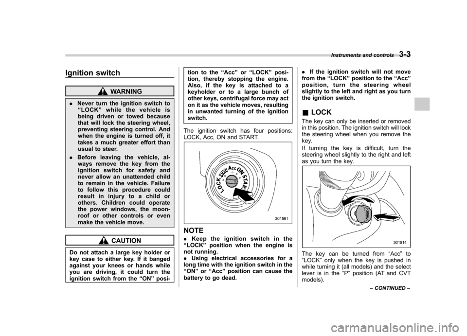
The ignition switch has four positions:
LOCK, Acc, ON and START.
NOTE . Keep the ignition switch in the
“ LOCK ”position when the engine is
not running. . Using electrical accessories for a
long time with the ignition switch in the“ ON ”or “Acc ”position can cause the
battery to go dead. .
If the ignition switch will not move
from the “LOCK ”position to the “Acc ”
position, turn the steering wheel
slightly to the left and right as you turn
the ignition switch. & LOCK
The key can only be inserted or removed
in this position. The ignition switch will lock
the steering wheel when you remove the
key.
If turning the key is difficult, turn the
steering wheel slightly to the right and left
as you turn the key.
The key can be turned from “Acc ”to
“ LOCK ”only when the key is pushed in
while turning it (all models) and the select
lever is in the “P ” position (AT and CVT
models). Instruments and controls
3-3
– CONTINUED –
Page 124 of 474
Hazard warning flasher
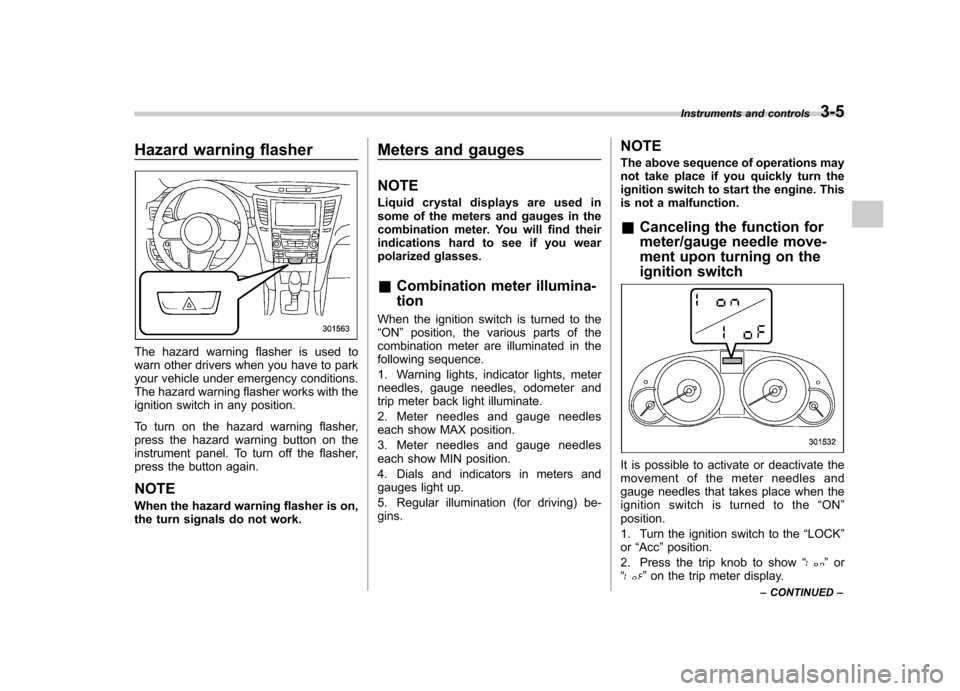
The hazard warning flasher is used to
warn other drivers when you have to park
your vehicle under emergency conditions.
The hazard warning flasher works with the
ignition switch in any position.
To turn on the hazard warning flasher,
press the hazard warning button on the
instrument panel. To turn off the flasher,
press the button again. NOTE
When the hazard warning flasher is on,
the turn signals do not work.Meters and gauges NOTE
Liquid crystal displays are used in
some of the meters and gauges in the
combination meter. You will find their
indications hard to see if you wear
polarized glasses. &
Combination meter illumina- tion
When the ignition switch is turned to the “ ON ”position, the various parts of the
combination meter are illuminated in the
following sequence.
1. Warning lights, indicator lights, meter
needles, gauge needles, odometer and
trip meter back light illuminate.
2. Meter needles and gauge needles
each show MAX position.
3. Meter needles and gauge needles
each show MIN position.
4. Dials and indicators in meters and
gauges light up.
5. Regular illumination (for driving) be- gins. NOTE
The above sequence of operations may
not take place if you quickly turn the
ignition switch to start the engine. This
is not a malfunction. &
Canceling the function for
meter/gauge needle move-
ment upon turning on the
ignition switch
It is possible to activate or deactivate the
movement of the meter needles and
gauge needles that takes place when the
ignition switch is turned to the “ON ”
position.
1. Turn the ignition switch to the “LOCK ”
or “Acc ”position.
2. Press the trip knob to show “
”or
“” on the trip meter display. Instruments and controls
3-5
– CONTINUED –
Page 126 of 474

possible to switch between the A trip
meter and B trip meter indications while
the odometer/trip meter is lit up. If you do
not press the trip knob within 10 seconds
of illumination of the odometer/trip meter,
the odometer/trip meter will turn off.
Also, if you open and close the driver’s
door within 10 seconds of illumination of
the odometer/trip meter, the odometer/trip
meter will turn off.
The display can be switched as shown in
the following illustration by pressing the
trip knob.
*1: “” or “”and “”or “”cannot
be displayed when the ignition switch is
in the “ON ”position.
*
2: MT models only
To set the trip meter to zero, select the A
trip or B trip meter by pressing the knob
and keep the knob pressed for more than
2 seconds.
CAUTION
To ensure safety, do not attempt to
change the function of the indicator
during driving, as an accident couldresult.
NOTE
If the connection between the combina-
tion meter and battery is broken for any
reason such as vehicle maintenance or
fuse replacement, the data recorded on
the trip meter will be lost. & Tachometer
The tachometer shows the engine speed
in thousands of revolutions per minute.
CAUTION
Do not operate the engine with the
pointer of the tachometer in the red
zone. In this range, fuel injection will
be cut by the engine control module
to protect the engine from overrev-
ving. The engine will resume run-
ning normally after the engine speed
is reduced below the red zone. NOTE
To protect the engine while the select
lever is in the
“P ” or “N ” position (for
AT and CVT models) or the shift lever is
in the neutral position (for MT models),
the engine is controlled so that the
engine speed may not become too high
even if the accelerator pedal is pressedhard.
& Fuel gauge
1) Low fuel warning light
The fuel gauge shows the approximate
amount of fuel remaining in the tank.
When the ignition switch is in the “LOCK ”
or “Acc ”position, the fuel gauge shows “E ”
even if the fuel tank contains fuel. Instruments and controls
3-7
– CONTINUED –
Page 128 of 474

Warning and indicator lights
Several of the warning and indicator lights
illuminate momentarily and then go out
when the ignition switch is initially turned
to the“ON ”position. This permits check-
ing the operation of the bulbs.
Apply the parking brake and turn the
ignition switch to the “ON ”position. For
the system check, the following lights
illuminate and turn off after several sec-
onds or after the engine has started:
: Seatbelt warning light (The seatbelt warning light turns off
only when the driver fastens the seatbelt.)
: Front passenger ’s seatbelt warning
light
(The seatbelt warning light turns off
only when the front seat passenger
fastens the seatbelt.)
: SRS airbag system warning light
ON /
: Front passenger ’s frontal airbag
ON indicator light
/: Front passenger ’s frontal airbag
OFF indicator light
: CHECK ENGINE warning light/Mal- function indicator light
: Coolant temperature high warning light
: Charge warning light
: Oil pressure warning light
: Engine low oil level warning light
: Windshield washer fluid warning light
: AT OIL TEMP warning light(AT and CVT models)
/: ABS warning light
: Vehicle Dynamics Control warning light/Vehicle Dynamics Control opera-
tion indicator light
: Vehicle Dynamics Control OFF indica-
tor light
/: Brake system warning light
: Hill Holder indicator light
: All-Wheel Drive warning light (AT andCVT models)
: Low tire pressure warning light (U.S. spec. models)
: Low fuel warning light
: Door open indicator light
: Cruise control indicator light
: Cruise control set indicator light
: Select lever/gear position indicator
If any lights fail to illuminate, it indicates a
burned-out bulb or a malfunction of the
corresponding system.
Consult your authorized SUBARU dealer
for repair. & Seatbelt warning light
and chime
Your vehicle is equipped with a seatbelt
warning device at the driver ’s and front
passenger ’s seat, as required by current
safety standards.
With the ignition switch turned to the “ON ”
position, this device reminds the driver
and front passenger to fasten their seat-
belts by the warning lights in the locations
indicated in the following illustration and achime. Instruments and controls
3-9
– CONTINUED –