2012 SUBARU OUTBACK screw
[x] Cancel search: screwPage 100 of 474
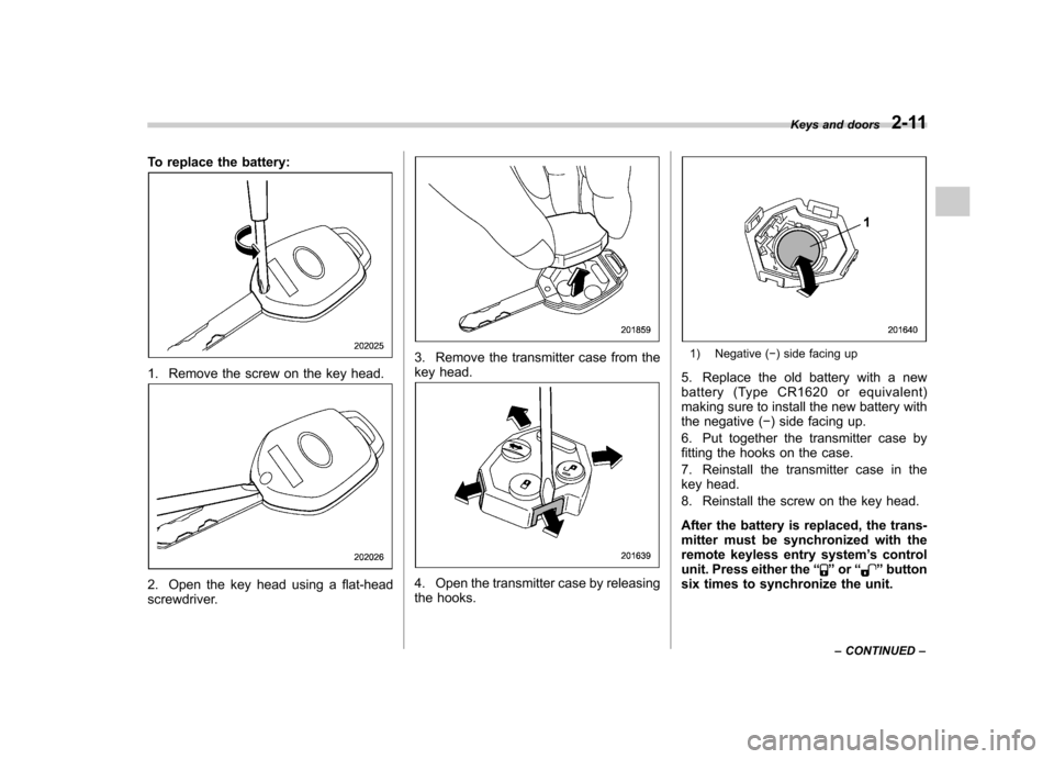
To replace the battery:
1. Remove the screw on the key head.
2. Open the key head using a flat-head
screwdriver.
3. Remove the transmitter case from the
key head.
4. Open the transmitter case by releasing
the hooks.
1) Negative (�) side facing up
5. Replace the old battery with a new
battery (Type CR1620 or equivalent)
making sure to install the new battery with
the negative ( �) side facing up.
6. Put together the transmitter case by
fitting the hooks on the case.
7. Reinstall the transmitter case in the
key head.
8. Reinstall the screw on the key head.
After the battery is replaced, the trans-
mitter must be synchronized with the
remote keyless entry system ’s control
unit. Press either the “
”or “”button
six times to synchronize the unit. Keys and doors
2-11
– CONTINUED –
Page 114 of 474

WARNING
Never allow any child to get in the
trunk and play with the release
handle. If the driver starts the vehi-
cle without knowing that a child is
inside the trunk and the child opens
the lid using the release handle, the
child could fall out and be killed or
seriously injured.
CAUTION
. Do not close the lid while grip-
ping the release handle. The
handle may be damaged.
. Do not use the handle as a hook
to fasten straps or ropes to
secure your cargo in the trunk.
Such use may result in damage
of the handle.
. Load the trunk so that cargo
cannot strike the release handle.
If the cargo hits the handle while
the vehicle is being driven, the
handle may be pulled and the
trunk lid may open. That may
cause cargo to fall out of the
trunk, which could create a traffic
safety hazard. !
Inspection
Perform the following steps at least twice
a year to check the release handle for
correct operation.
1. Open the trunk lid.
2. Use a flat-head screwdriver with a thin
blade. Slide the flat-head screwdriver
blade from the slit aperture of the lock
assembly fully to the end until you hear a click.
This places the latch in the locked posi- tion.
3. Move the release handle, from outside
the vehicle, in the direction of the arrow to
check if the latch is released. Keys and doors
2-25
– CONTINUED –
Page 291 of 474
7-14Starting and operating
will flash one time.
7. Repeat step 5 for any additional
transmitters (the system will accept up to
eight transmitters).
8. The system will exit the transmitter
learn mode if the key is turned to the“LOCK ”position, the door is closed or
after 2 minutes. & System maintenance
NOTE
In the event that the vehicle ’s battery is
replaced, discharged or disconnected,
it will be necessary to start the vehicle
a minimum of one time using the key
prior to activating the remote engine
start system. This is required to allow
the vehicle electronic systems to re-synchronize. ! Changing the batteries
CAUTION
. Do not let dust, oil or water get on
or in the remote engine start
transmitter when replacing the
battery.
. Be careful not to damage the
printed circuit board in the re-
mote engine start transmitter
when replacing the battery. .
Be careful not to allow children to
touch the battery and any re-
moved parts; children could
swallow them.
. There is a danger of explosion if
an incorrect replacement battery
is used. Replace only with the
same or equivalent type of bat-
tery.
. Batteries should not be exposed
to excessive heat such as sun-
shine, fire or the like.
The two 3-volt lithium batteries (model
CR-2032) supplied in your remote engine
start transmitter should last approximately
one year, depending on usage. When the
batteries begin to weaken, you will notice
a decrease in range (distance from the
vehicle that your remote control operates).
Follow the instructions below to change
the remote engine start transmitter bat-teries.
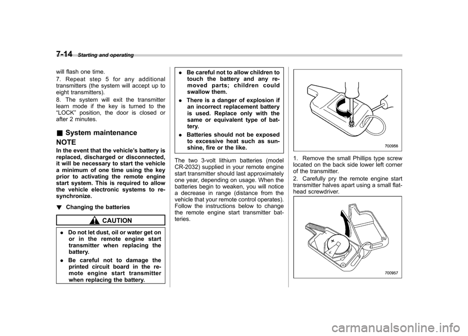
1. Remove the small Phillips type screw
located on the back side lower left corner
of the transmitter.
2. Carefully pry the remote engine start
transmitter halves apart using a small flat-
head screwdriver.
Page 292 of 474
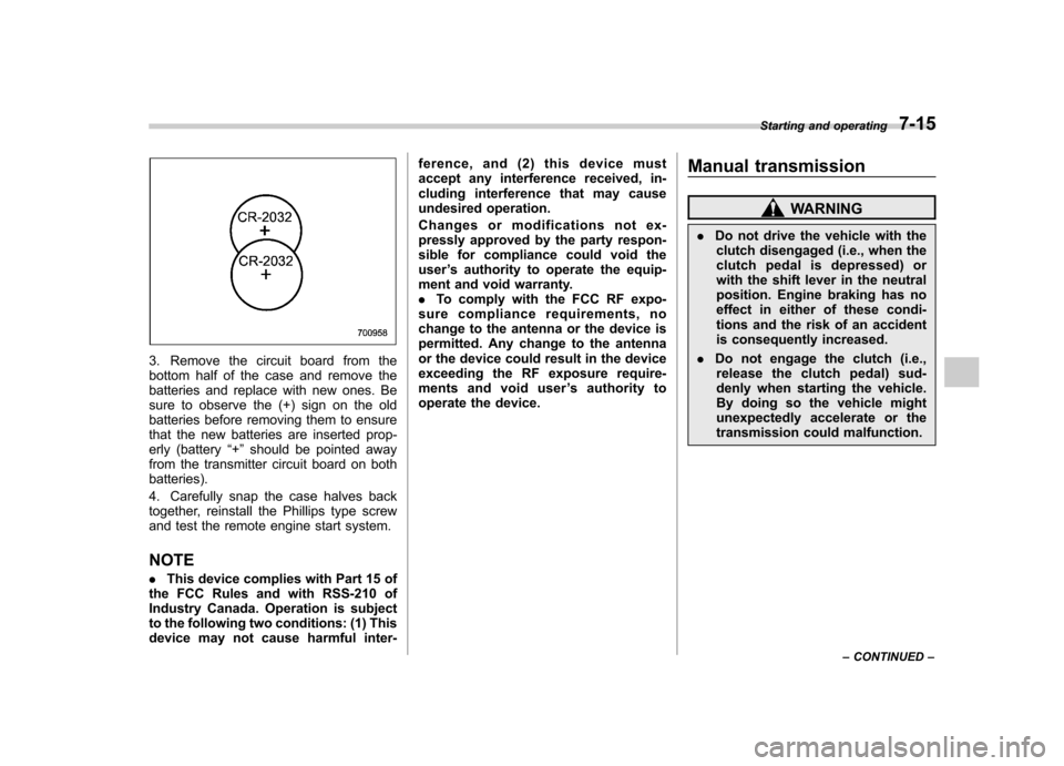
3. Remove the circuit board from the
bottom half of the case and remove the
batteries and replace with new ones. Be
sure to observe the (+) sign on the old
batteries before removing them to ensure
that the new batteries are inserted prop-
erly (battery“+ ” should be pointed away
from the transmitter circuit board on bothbatteries).
4. Carefully snap the case halves back
together, reinstall the Phillips type screw
and test the remote engine start system. NOTE . This device complies with Part 15 of
the FCC Rules and with RSS-210 of
Industry Canada. Operation is subject
to the following two conditions: (1) This
device may not cause harmful inter- ference, and (2) this device must
accept any interference received, in-
cluding interference that may cause
undesired operation.
Changes or modifications not ex-
pressly approved by the party respon-
sible for compliance could void theuser
’s authority to operate the equip-
ment and void warranty.. To comply with the FCC RF expo-
sure compliance requirements, no
change to the antenna or the device is
permitted. Any change to the antenna
or the device could result in the device
exceeding the RF exposure require-
ments and void user ’s authority to
operate the device. Manual transmission
WARNING
. Do not drive the vehicle with the
clutch disengaged (i.e., when the
clutch pedal is depressed) or
with the shift lever in the neutral
position. Engine braking has no
effect in either of these condi-
tions and the risk of an accident
is consequently increased.
. Do not engage the clutch (i.e.,
release the clutch pedal) sud-
denly when starting the vehicle.
By doing so the vehicle might
unexpectedly accelerate or the
transmission could malfunction. Starting and operating
7-15
– CONTINUED –
Page 297 of 474
7-20Starting and operating
NOTE
The transmission may downshift, de-
pending on the way the accelerator
pedal is depressed to accelerate the
vehicle again. & Shift lock function
The shift lock function helps prevent the
improper operation of the select lever. . The select lever cannot be operated
unless the ignition switch is turned to the “ ON ”position and the brake pedal is
depressed. . The select lever cannot be moved from
the “P ” position to any other position
before the brake pedal is depressed.
Depress the brake pedal first, and then
operate the select lever. . Only the “P ”position allows you to turn
the key from the “Acc ”position to the
“ LOCK ”position and remove the key from
the ignition key cylinder.. If the ignition switch is turned to the
“ LOCK ”position while the select lever is in
the “N ”position, the select lever may not
be moved to the “P ”position after a period
of time. Therefore, move the select lever
to the “P ” position with the brake pedal
depressed soon after the ignition switch is
turned to the “LOCK ”position. !
Shift lock release
If the select lever cannot be operated, turn
theignitionswitchbacktothe “ON ”
position then move the select lever to the“ P ” position with the select lever button
pressed and brake pedal depressed.
If the select lever does not move after
performing the above procedure, perform
the following steps. . When the select lever cannot be
shifted from “P ” to “N ”:
Refer to “Shift lock release using the shift
lock release button ”F 7-20.
. When the select lever cannot be
shifted from “N ” to “R ”, “P ”:
Within 60 seconds after placing the igni-
tion switch in the “Acc ”position, move the
select lever to the “P ” position with the
select lever button pressed and brake
pedal depressed.
If you must perform the above procedure,
the shift lock system (or the vehicle control
system) may be malfunctioning. Contact a
SUBARU dealer for an inspection as soon
as possible.
If the select lever does not move after
performing the above procedure, refer to“ Shift lock release using the shift lock
release button ”F 7-20. !
Shift lock release using the shift
lock release button
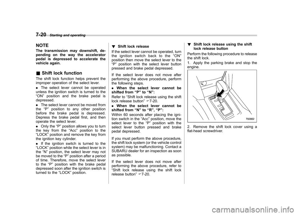
Perform the following procedure to release
the shift lock.
1. Apply the parking brake and stop the engine.
2. Remove the shift lock cover using a
flat-head screwdriver.
Page 298 of 474
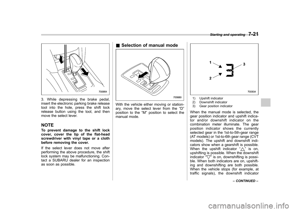
3. While depressing the brake pedal,
insert the electronic parking brake release
tool into the hole, press the shift lock
release button using the tool, and then
move the select lever. NOTE
To prevent damage to the shift lock
cover, cover the tip of the flat-head
screwdriver with vinyl tape or a cloth
before removing the cover.
If the select lever does not move after
performing the above procedure, the shift
lock system may be malfunctioning. Con-
tact a SUBARU dealer for an inspection
as soon as possible.&
Selection of manual mode
With the vehicle either moving or station-
ary, move the select lever from the “D ”
position to the “M ”position to select the
manual mode.
1) Upshift indicator
2) Downshift indicator
3) Gear position indicator
When the manual mode is selected, the
gear position indicator and upshift indica-
tor and/or downshift indicator on the
combination meter illuminate. The gear
position indicator shows the currently
selected gear in the 1st-to-5th-gear range
(AT models) or 1st-to-6th gear range (CVT
models). The upshift and downshift indi-
cators show when a gearshift is possible.
When the upshift indicator “
”is on,
upshifting is possible. When the downshift indicator “
”is on, downshifting is possi-
ble. When both indicators are on, upshift-
ing and downshifting are both possible.
When the vehicle stops (for example, at
traffic signals), the downshift indicator Starting and operating
7-21
– CONTINUED –
Page 346 of 474

CAUTION
Never use any temporary spare tire
other than the original. Using other
sizes may result in severe mechan-
ical damage to the drive train of yourvehicle.
The temporary spare tire is smaller and
lighter than a conventional tire and is
designed for emergency use only. Re-
move the temporary spare tire and re-
install the conventional tire as soon as
possible because the spare tire is de-
signed only for temporary use.
Check the inflation pressure of the tem-
porary spare tire periodically to keep the
tire ready for use. The correct pressure is
60 psi (420 kPa, 4.2 kgf/cm
2) .
When using the temporary spare tire, note
the following precautions. . Do not exceed 50 mph (80 km/h).
. Do not put a tire chain on the temporary
spare tire. Because of the smaller tire size,
a tire chain will not fit properly. . Do not use two or more temporary
spare tires at the same time.. Do not drive over obstacles. This tire
has a smaller diameter, so road clearance
is reduced.
1) Tread wear indicator bar
2) Indicator location mark
. When the wear indicator appears on
the tread, replace the tire. . The temporary spare tire must be used
only on a rear wheel. If a front wheel tire
gets punctured, replace the wheel with a
rear wheel and install the temporary spare
tire in place of the removed rear wheel. Maintenance tools
Your vehicle is equipped with the following
maintenance tools. .
Jack
. Jack handle
. Screwdriver
. Towing hook (eye bolt) (if equipped)
. Wheel nut wrench
. Electronic parking brake release tool In case of emergency
9-3
– CONTINUED –
Page 347 of 474
9-4In case of emergency
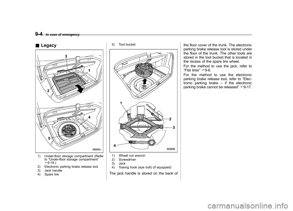
& Legacy
1) Under-floor storage compartment (Refer
to“Under-floor storage compartment ”
F 6-18.)
2) Electronic parking brake release tool
3) Jack handle
4) Spare tire 5) Tool bucket1) Wheel nut wrench
2) Screwdriver
3) Jack
4) Towing hook (eye bolt) (if equipped)
The jack handle is stored on the back of the floor cover of the trunk. The electronic
parking brake release tool is stored under
the floor of the trunk. The other tools are
stored in the tool bucket that is located in
the recess of the spare tire wheel.
For the method to use the jack, refer to “
Flat tires ”F 9-6.
For the method to use the electronic
parking brake release tool, refer to “Elec-
tronic parking brake –if the electronic
parking brake cannot be released ”F 9-17.