Page 148 of 715
01-6
3. ENGINE COMPARTMENT LAYOUT
Do not work on the engine compartment while the engine, radiator, exhaust manifold, muffler
or catalytic converter is hot. Always turn the engine off and allow it to cool before starting the
maintenance.
Regularly check the engine oil level and add Ssangyong genuine engine oil if necessary.
Clean the dipstick with clean cloth so that any foreign materials cannot get into the engine. -
-
-
Power steering fluid
reservoir Brake fluid reservoir
Engine oil
dipstick gauge
Washer fluid
reservoir cap Engine oil filler cap
Air cleaner
Operating vehicle with insuffi cient amount of oil can damage the engine. Make sure the
engine oil level is correct and add oil if necessary.
Coolant reservoir
Battery
Fuse & relay
Page 258 of 715

06-171914-01
1. SYSTEM DESCRIPTION OF E-VGT
(Electric-Variable Geometry Turbine)
The E-VGT turbocharger has one shaft where at each ends are installed with two turbines having
different angles to connect one end of housing to the intake manifold and the other end to the
exhaust manifold. As the turbine, at exhaust end, is rotated by exhaust gas pressure the impeller,
at intake end, gets rotated to send air around center of the impeller, being circumferentially
accelerated by the centrifugal force, into the diffuser. The air, which has been introduced to the
diffuser having a passage with big surface, transforms its speed energy into the pressure energy
while being supplied to the cylinder improving the volume efficiency.
Also, the exhaust efficiency improves as the exhaust turbine rotates. The turbocharger is often
referred to as the exhaust turbine turbocharger.
Diffuser: With the meaning of spreading out it is a device that transforms fluid's speed energy into
the pressure energy by enlarging the fluid's passage to slow down the flow.
The E-VGT system installed to the D20DTR engine variably controls the passages of the turbine
housing to regulate the flow rate of the exhaust gas. The actuator of E-VGT is a DC motor
actuator (EActuator) which controls more quickly and precisely than the previous vacuum type
actuator.
Page 277 of 715

09-51451-01
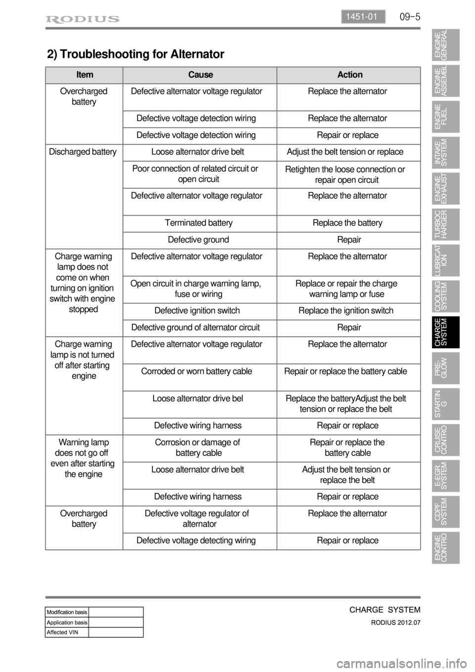
2) Troubleshooting for Alternator
Item Cause Action
Overcharged
batteryDefective alternator voltage regulator Replace the alternator
Defective voltage detection wiring Replace the alternator
Defective voltage detection wiring Repair or replace
Discharged battery Loose alternator drive belt Adjust the belt tension or replace
Poor connection of related circuit or
open circuitRetighten the loose connection or
repair open circuit
Defective alternator voltage regulator Replace the alternator
Terminated battery Replace the battery
Defective ground Repair
Charge warning
lamp does not
come on when
turning on ignition
switch with engine
stoppedDefective alternator voltage regulator Replace the alternator
Open circuit in charge warning lamp,
fuse or wiringReplace or repair the charge
warning lamp or fuse
Defective ignition switch Replace the ignition switch
Defective ground of alternator circuit Repair
Charge warning
lamp is not turned
off after starting
engineDefective alternator voltage regulator Replace the alternator
Corroded or worn battery cable Repair or replace the battery cable
Loose alternator drive bel Replace the batteryAdjust the belt
tension or replace the belt
Defective wiring harness Repair or replace
Warning lamp
does not go off
even after starting
the engineCorrosion or damage of
battery cableRepair or replace the
battery cable
Loose alternator drive belt Adjust the belt tension or
replace the belt
Defective wiring harness Repair or replace
Overcharged
batteryDefective voltage regulator of
alternatorReplace the alternator
Defective voltage detecting wiring Repair or replace
Page 295 of 715
11-4
2. TROUBLESHOOTING
Problem Possible Cause Action
Engine will not crankLow battery voltage Charge or replace
Loose, corroded or damaged battery cable
Repair or replace
Faulty starter or open circuit
Faulty ignition switch or blown fuseRepair or replace
Poor engine ground Repair
Engine cranks too
slowLow battery voltage Charge or replac
Loose, corroded or damaged battery cable
Repair or replace Faulty starter
Starter does not
stopFaulty starter
Faulty ignition switch Replace
Engine cranks
normally, but does
not startBroken pinion gear or faulty starter
Replace the starter
Broken flywheel ring gear Replace
Open circuit Repair
Page 367 of 715
15-42
(13) PTC heater control
A. Overview
The supplementary electrical heater is installed in DI engine equipped vehicle as a basic equipment. The
PTC system is operated according to two temperature values measured at the coolant temperature
sensor and HFM sensor. This device is mounted in the heater air outlet and increase the temperature of
air to the passenger compartment. Because PTC system is heated by electrical power, high capacity
alternator is required. PTC does not operate during engine cranking, while the battery voltage is lower
than 11 V or during preheating process of glow plugs.
B. Components
HFM (intake air
temperature)
Coolant temperature
sensor
PTC relay 1
D20DTR ECU
PTC relay 2
PTC fuse 1, 2, 3, 40A
PTC heater
PTC Fuse and Relay
Page 417 of 715
01-38410-02
1. CAUTIONS WHEN WORKING ON ELECTRICAL UNITS
80℃
10A 15A
Disconnect the negative cable from the
battery in advance when working on
electrical units. -
Make sure to turn "OFF" the ignition switch
and other lamp switches before
disconnecting or connecting the negative
battery cable. (Otherwise, semiconductor
parts can be damaged.)
Do not drop or appy excessive impact to
sensors and relays. -
If a fuse is blown, replace it with a fuse
which has the correct amperage rating. If
you use a fuse with higher capacity than
the specification, the component can be
damaged or catch fire. -
Page 420 of 715
01-6
1. OVERVIEW
The fuse and relay boxes consist of four boxes: Fuse & relay box, in engine room and Fuse and
relay box in left side of instrument panel.
2. LOCATION
▶Engine Room Fuse and Relay Box
▶Interior Fuse and Relay Box
PTC Box Assembly
Page 421 of 715
01-78410-02
3. CIRCUIT DIAGRAM
▶SB1~SB4, C/FAN (HI,LO) REALY, F/HEATER RELAY, C/FAN (SUB) RELAY
1) Engine Room Fuse and Relay Box