Page 541 of 715

02-33170-01
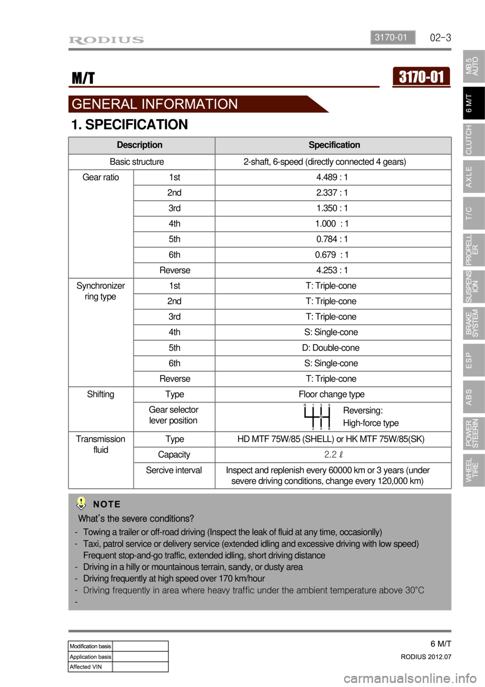
Description Specification
Basic structure 2-shaft, 6-speed (directly connected 4 gears)
Gear ratio 1st 4.489 : 1
2nd 2.337 : 1
3rd 1.350 : 1
4th 1.000 : 1
5th 0.784 : 1
6th 0.679 : 1
Reverse 4.253 : 1
Synchronizer
ring type1st T: Triple-cone
2nd T: Triple-cone
3rd T: Triple-cone
4th S: Single-cone
5th D: Double-cone
6th S: Single-cone
Reverse T: Triple-cone
Shifting Type Floor change type
Gear selector
lever position
Transmission
fluidType HD MTF 75W/85 (SHELL) or HK MTF 75W/85(SK)
Capacity2.2 ℓ
Sercive interval Inspect and replenish every 60000 km or 3 years (under
severe driving conditions, change every 120,000 km)
1. SPECIFICATION
Reversing:
High-force type
What’s the severe conditions?
Towing a trailer or off-road driving (Inspect the leak of fluid at any time, occasionlly)
Taxi, patrol service or delivery service (extended idling and excessive driving with low speed)
Frequent stop-and-go traffic, extended idling, short driving distance
Driving in a hilly or mountainous terrain, sandy, or dusty area
Driving frequently at high speed over 170 km/hour
<006b00990090009d00900095008e0047008d0099008c0098009c008c0095009b009300a0004700900095004700880099008c00880047009e008f008c0099008c0047008f008c0088009d00a00047009b00990088008d008d0090008a0047009c0095008b00
8c00990047009b008f008c00470088009400890090008c0095>t temperature above 30°C -
-
-
-
-
-
Page 542 of 715
02-4
2. MAJOR CHANGES
New Transmission (6-speed M/T)
Old (5-speed M/T) New (6-speed M/T)
To maximize the performance of D20DTR engine, new 6-speed manual transmission has been
introduced for 2012 Model.
Rear Mounting Insulator
2WD 6M/T 2WD A/T 4WD A/T
P/N : 3190021M20 P/N : 3190021A20 P/N : 3190021A40
There are three types of rear mounting insulators according to the variations of transmission.
Page 546 of 715
02-8
3163161-00 Housing ▶
Case - Transmission
Retainer - Bearing
Bolt - Seal (19.6 ~ 24.5 Nm)
Seal - Oil
Bushing
Spacer
Gasket
Plug (58.8 ~ 78.4 Nm)
Gasket
Plug 2.
3.
4.
5.
6.
7.
8.
9.
10.
11.Breather - Air
Pulg - Seal (53.9 ~ 67.6 Nm)
Cylinder assembly - Concentric slave
Plunger - Rolling
Boot
Guide - Oil
Spring - Guide
Bolt - Flange (42.1 ~ 53.9 Nm) 12.
13.
14.
15.
16.
17.
18.
19.
Page 553 of 715
02-153170-01
Sectional viewFront view
1. OVERVIEW
1) Characteristics of Transmission
Forward and Reverse gears are helical gear.
The clutch is operated by concentric slave cylinder (CSC).
To prevent the improper gear shift, semi-remote control system has been introduced.
To prevent the gears from engaging improperly, the synchronizer mechanisms and
independent interlock systems are installed on 1/2 gears, 3/4 gears, 5/6 gears and reverse
gear.
The High-Force system for reverse gear shift has been introduced.
The synchronizer has three types: Triple (1, 2, 3, R), Double (5), Single (4, 6) -
-
-
-
-
-
6-speed M/T
Page 554 of 715
02-16
2) Sectional Diagram
3) Gear Ratio
Transmission housing
Extension housing
Main shaft Counter shaft Main drive gearIntermediate plate
GearTeeth
Final gear ratio
Input Output
1st 13 38 4.489
2nd 23 35 2.337
3rd 33 29 1.350
4th 28 43 1.000
5th 47 24 0.784
6th 52 23 0.679
R 13 36 4.253
IDLE : 25
Page 566 of 715

03-93010-00
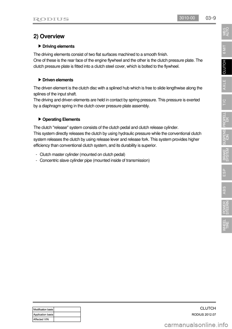
2) Overview
Driving elements ▶
The driving elements consist of two flat surfaces machined to a smooth finish.
One of these is the rear face of the engine flywheel and the other is the clutch pressure plate. The
clutch pressure plate is fitted into a clutch steel cover, which is bolted to the flywheel.
Driven elements ▶
The driven element is the clutch disc with a splined hub which is free to slide lengthwise along the
splines of the input shaft.
The driving and driven elements are held in contact by spring pressure. This pressure is exerted
by a diaphragm spring in the clutch cover pressure plate assembly.
Operating Elements ▶
The clutch "release" system consists of the clutch pedal and clutch release cylinder.
This system directly releases the clutch by using hydraulic pressure while the conventional clutch
system releases the clutch by using release lever and release fork. This system provides higher
efficiency than conventional clutch system, and its durability is superior.
Clutch master cylinder (mounted on clutch pedal)
Concentric slave cylinder pipe (mounted inside of transmission) -
-
Page 568 of 715
03-113010-00
3. DUAL MASS FLYWHEEL (DMF)
The dual mass flywheel (DMF) is of having a mass divided into two halves.
While one mass is connected to the engine crankshaft, which is affected by the mass moment of
inertia of the engine, the other mass is affected by one of the transmission.
The divided dual masses are connected to the coil spring and damping system internally.
The DMF has the following benefits: ▶
Reducing fuel consumption by lowering engine speed
Reducing rattling noise and vehicle vibration in all driving ranges
Reducing synchronization wear
Facilitating gear change
Protecting power train parts by preventing excessive load from being delivered -
-
-
-
-
Primary flywheel
Secondary flywheel
Arc damper spring
Torque limiter
Ring gear 1.
2.
3.
4.
5.
Page 573 of 715

05-6
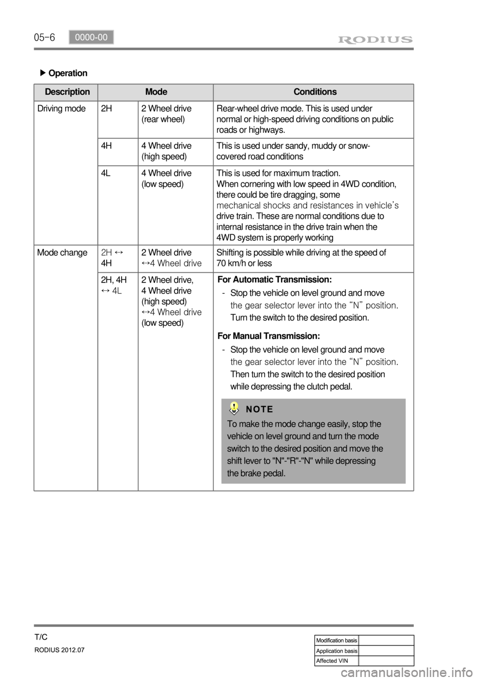
Operation ▶
Description Mode Conditions
Driving mode 2H 2 Wheel drive
(rear wheel)Rear-wheel drive mode. This is used under
normal or high-speed driving conditions on public
roads or highways.
4H 4 Wheel drive
(high speed)This is used under sandy, muddy or snow-
covered road conditions
4L 4 Wheel drive
(low speed)This is used for maximum traction.
When cornering with low speed in 4WD condition,
there could be tire dragging, some
mechanical shocks and resistances in vehicle’s
drive train. These are normal conditions due to
internal resistance in the drive train when the
4WD system is properly working
Mode change2H ↔
4H 2 Wheel drive
↔4 Wheel driveShifting is possible while driving at the speed of
70 km/h or less
2H, 4H
↔ 4L 2 Wheel drive,
4 Wheel drive
(high speed)
↔4 Wheel drive
(low speed)
To make the mode change easily, stop the
vehicle on level ground and turn the mode
switch to the desired position and move the
shift lever to "N"-"R"-"N" while depressing
the brake pedal. For Automatic Transmission:
Stop the vehicle on level ground and move
the gear selector lever into the “N” position.
Turn the switch to the desired position. -
For Manual Transmission:
Stop the vehicle on level ground and move
the gear selector lever into the “N” position.
Then turn the switch to the desired position
while depressing the clutch pedal. -