Page 163 of 715
02-6
Cylinder head coverM6×352110±1Nm-
Oil gauge tubeM6×16110±1Nm-
Oil filter cap 125±2.5Nm-
Fuel railM8×25225±2.5Nm-
Injector clamp boltM6×4429±1.0Nm
130˚±10˚-
High pressure pipe
(between HP pump and
fuel rail)M17 130±3Nm-
High pressure pipe
(between fuel rail and
injector)M17 430±3Nm-
Crank position sensorM5×1418±0.4Nm-
Main wiringM6×16510±1Nm-
Intake ductM8×25325±2.5Nm-
Power steering pumpM8×100325±2.5Nm-
Cylinder head front
coverM6×10510±1Nm-
Ladder frame M8x16 530±3Nm-
Component SizeBolt
QuantitySpecified torque
(Nm)Remark
(Total torque)
Glow plug M5 420±2Nm-
Vacuum pumpM8×25310±1Nm-
Timing gear case coverM6×40710±1Nm-
M6×45110±1Nm-
M6×50310±1Nm-
Page 169 of 715

02-12
Electrical equipment ▶
Electric devices should be handled more carefully.
Currently, the engine has a lot of electric devices. there could be poor engine performance,
incomplete combustion and other abnormal symptoms due to short circuit or poor contact.
Before work on engine and each electrical equipment, be sure to disconnect battery negative
(-) terminal.
When replacing the electric device, use only genuine part and check the conditions of
connections and grounds. Loosened connection or ground make cause a fire and personal
injury. -
-Fuel and lubrication system ▶
Do not allow the fluid and engine oil to make contact with the body paintwork and hoses.
If work on the fluid system such as fuel and oil, working area should be well ventilated and
smoking should be prohibited.
Gasket or seal on the fuel/lubrication system should be replaced with new ones and bolts and
nuts should be tightened as specified.
After removal/installation works, be sure to check whether there is leak on the connecting
section. -
-
-
-
If fine dust or foreign material enters into DI engine's fuel system, there can be serious damages
in HP pump and injectors. Thus, be sure to plug the inlets of removed fuel line components with
cap and protect removed parts not to be contaminated with dirt. (Refer to cleanness in this
manual while working on DI engine fuel system)
Page 178 of 715
02-210000-00
4. INTAKE/EXHAUST MANIFOLD
1) Intake Manifold
Intake manifold is installed on the cylinder head with 8 bolts. The variable swirl valve is introduced to
improve the EGR gas mixture and turbulence in combustion chamber and to decrease the exhaust
gas.
2) Exhaust Manifold
Exhaust manifold is installed on the cylinder head with 10 stud bolts and nuts. EGR port is integrated
in cylinder head.Components ▶
Components ▶For detailes, refer to Chapter "Intake System". *
For detailes, refer to Chapter "Exhaust System". *
Exhaust manifold
Intake manifold
Page 186 of 715
02-290000-00
1) Chain Drive
(1) Overview
The drive chain is single chain drive system with simple design and variable performance, and it
utilizes the hydraulic tensioner to reduce the wave impact generated by the chain. This chain is light
weight and has high durability through single bush chain. Shoulder bolts are used for better NHV.
7. CHAIN AND GEAR DRIVE SYSTEM
D20DTR engine uses single stage chain drive system. Timing chain drives the exhaust side and
gear drive the intake side. Timing chain is single bush type. Upper chain drives HP pump
connected to intake Camshaft by driving exhaust cam shift sprocke, and lower chain drives oil
pump to lubricate the engine.
Page 200 of 715
02-430000-00
2) Connecting Rod
(1) Overview
Connecting rod converts the reciprocating movement of piston to the rotating movement of
crankshaft. The big end is connected to connecting rod bearing and the crank pin journal, and the
small end is connected to the piston pin.
(2) Components
Connecting rod cap bolt
Connecting rod upper bearing
Connecting rod
Piston pin bush
Connecting lower bearing
Connecting rod cap
Page 209 of 715

03-52210-01
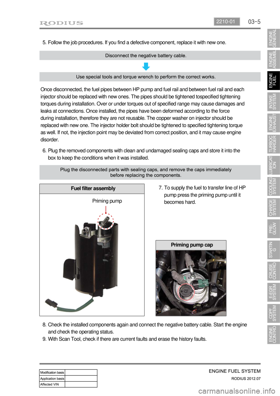
Plug the removed components with clean and undamaged sealing caps and store it into the
box to keep the conditions when it was installed. 6.
Fuel filter assembly
Follow the job procedures. If you find a defective component, replace it with new one. 5.
Once disconnected, the fuel pipes between HP pump and fuel rail and between fuel rail and each
injector should be replaced with new ones. The pipes should be tightened tospecified tightening
torques during installation. Over or under torques out of specified range may cause damages and
leaks at connections. Once installed, the pipes have been deformed according to the force
during installation, therefore they are not reusable. The copper washer on injector should be
replaced with new one. The injector holder bolt should be tightened to specified tightening torque
as well. If not, the injection point may be deviated from correct position, and it may cause engine
disorder.
To supply the fuel to transfer line of HP
pump press the priming pump until it
becomes hard. 7.
Priming pump
Check the installed components again and connect the negative battery cable. Start the engine
and check the operating status.
With Scan Tool, check if there are current faults and erase the history faults. 8.
9.
Priming pump cap
Page 246 of 715

06-51914-01
2) Inspection of Turbocharger
When problem occurs with the turbocharger, it could cause engine power decline, excessive
discharge of exhaust gas, outbreak of abnormal noise and excessive consumption of oil.
On-board Inspection 1.
Check the bolts and nuts foe looseness or missing
Check the intake and exhaust manifold for looseness or damage
Check the oil supply pipe and drain pipe for damages
Check the housing for crack and deterioration -
-
-
-
Inspection of turbine 2.
Remove the exhaust pipe at the opening of the turbine and check, with a lamp, the existence of
interference of housing and wheel, oil leakage and contamination (at blade edge) of foreign
materials.
Interference: In case where the oil leak sign exists, even the small traces of interferences on
the turbine wheel mean, most of times, that abrasion has occurred on the journal bearing.
Must inspect after overhauling the turbocharger.
Oil Leakage: Followings are the reasons for oil leakage condition -
-
Problems in engine: In case where the oil is smeared on inner wall section of the exhaust
gas opening.
Problems in turbocharger: In case where the oil is smeared on only at the exhaust gas
outlet section. *
*
Idling for long period of time can cause oil leakage to the turbine side due to low pressure of
exhaust gas and the rotation speed of turbine wheel. Please note this is not a turbocharger
problem.
Oil Drain Pipe Defect
In case where oil flow from the turbocharger sensor housing to the crank case is not smooth
would become the reason for leakage as oil builds up within the center housing. Also, oil
thickens (sludge) at high temperature and becomes the indirect reason of wheel hub section.
In such case, clogging and damage of the oil drain pipe and the pressure of blow-by gas
within the crank case must be inspected.
Damages due to Foreign Materials.
When the foreign materials get into the system, it could induce inner damage as rotating
balance of the turbocharger gets out of alignment. -
-
-
Page 252 of 715

06-111914-01
3. TROUBLESHOOTING
The followings are cautions to take in handling defects of turbocharger, which must be fully aware
of.
1) Cautions
After stopping the engine, check whether the bolts on pipe connecting section are loose as
well as the connecting condition of vacuum port and modulator, which is connected to the
actuator.
During idling of the engine, check for leakage in the connecting section of pipe (hoses and
pipes, duct connections, after the turbocharger) by applying soap water. The leakage condition
in the engine block and turbine housing opening can be determined by the occurrence of
abnormal noise of exhaust.
By running the engine at idle speed, abnormal vibration and noise can be checked.
Immediately stop the engine when abnormal vibration and noise is detected and make
thorough inspection whether the turbocharger shaft wheel has any damages as well as
checking the condition of connections between pipes.
In case where the noise of engine is louder than usual, there is possibility of dampness in the
areas related with air cleaner and engine or engine block and turbocharger. And it could affect
the smooth supply of engine oil and discharge.
Check for damp condition in exhaust gas when there is sign of thermal discoloration or
discharge of carbon in connecting area of the duct.
When the engine rotates or in case where there is change in noise level, check for clogging of
air cleaner or air cleaner duct or if there is any significant amount of dust in the compressor
housing.
During the inspection of center housing, inspect inside of the housing by removing the oil drain
pipe to check for sludge generation and its attachment condition at shaft area or turbine side.
Inspect or replace the air cleaner when the compressor wheel is damaged by inflow of foreign
materials.
Inspect both side of the turbocharger wheel after removing inlet and outlet pipe of the
turbocharger. 1.
2.
3.
4.
5.
6.
7.
8.
9.