Page 228 of 715

03-24
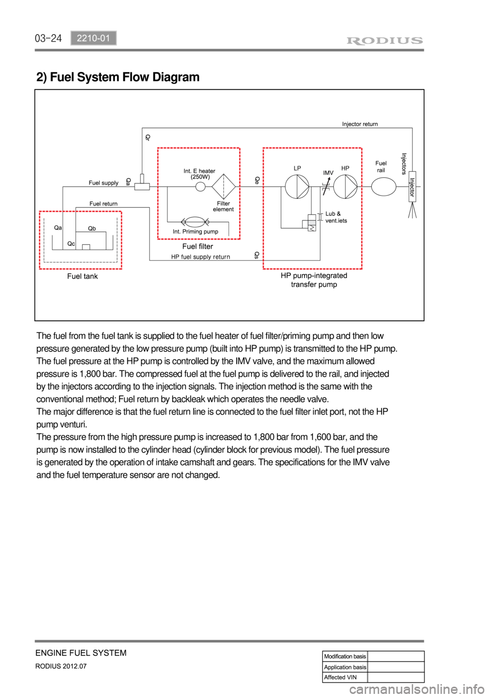
2) Fuel System Flow Diagram
The fuel from the fuel tank is supplied to the fuel heater of fuel filter/priming pump and then low
pressure generated by the low pressure pump (built into HP pump) is transmitted to the HP pump.
The fuel pressure at the HP pump is controlled by the IMV valve, and the maximum allowed
pressure is 1,800 bar. The compressed fuel at the fuel pump is delivered to the rail, and injected
by the injectors according to the injection signals. The injection method is the same with the
conventional method; Fuel return by backleak which operates the needle valve.
The major difference is that the fuel return line is connected to the fuel filter inlet port, not the HP
pump venturi.
The pressure from the high pressure pump is increased to 1,800 bar from 1,600 bar, and the
pump is now installed to the cylinder head (cylinder block for previous model). The fuel pressure
is generated by the operation of intake camshaft and gears. The specifications for the IMV valve
and the fuel temperature sensor are not changed.
Page 234 of 715
04-6
1. OVERVIEW
The intake system for D20DTR engine is equipped with a throttle body which includes a flap. This
flap is controlled by an electrical signal to cut off the intake air entering to the engine when the
ignition switch is turned off. Because of this, the shape of the intake manifold has been changed
and improved HFM sensor is newly adopted to control the intake air volume more precisely.
2. COMPONENT
2330-01 Intercooler assembly
2313-15 HFM sensor
HFM sensor, version 7
*For more information, refer to Chapter "Engine
Control".
2313-01 Air cleaner assembly
Page 266 of 715
07-51543-00
1. SYSTEM DESCRIPTION
1) Overview
The lubrication system supplies oil to each lubrication section to prevent friction and wear and to
remove heat from the friction part. As the engine runs, frictional heat is generated on each
lubrication section. If this condition persists, the bearing can be burned and stuck.
In other words, it creates an oil film on each sliding surface to convert solid friction to liquid
friction in order to minimize wear and prevent temperature increasing on the friction part.
For the D20DTF engine with no oil pressure switch, the engine ECU receives the low engine oil
level signal from the oil level sensor and communicates with the instrument cluster through the
CAN communication to turn on the warning lamp.
2) Components
Oil coolerOil dipstick gaugeOil pump
Oil filter moduleOil pressure switchOil pan
Page 307 of 715

12-12
Do not move the shift lever to Neutral position while driving with the cruise control turned on.
Otherwise, it may result in system malfunction or accidents.
Always be prepared to use the brake or accelerator pedal for safe driving while the cruise
control system is running.
The actual speed can be different from the set speed momentarily when driving on a uphill
or downhill. So, it is recommended to disable the cruise control function on a uphill or
downhill. hen driving on a steep hill use the engine brake and foot brake properly to protect
the vehicle system and for a safe driving.
Ensure that the safe distance is maintained and use the brake pedal if needed. 1.
2.
3.
4.
(1) Abnormal Cancellation of the Cruise Control
When the rapid deceleration is applied without braking.
When the rapid acceleration is applied without acceleration pedal intervention.
When the cruise control lever is faulty.
When the brake switch and the brake light switch input signal are implausible. 1.
2.
3.
When the cruise control function is cancelled abnormally or intermittent problems occur, stop the
vehicle and turn off the ignition switch and remove the key to reset the system. After a while, turn
on the ignition switch again to operate the cruise control system.
Page 336 of 715

15-110000-00
2) ECU Control
(1) Function
a. ECU Function
ECU receives and analyzes signals from various sensors and then modifies those signals into
permissible voltage levels and analyzes to control respective actuators.
ECU microprocessor calculates injection period and injection timing proper for engine piston speed and
crankshaft angle based on input data and stored specific map to control the engine power and emission
gas.
Output signal of the ECU microprocessor drives pressure control valve to control the rail pressure and
activates injector solenoid valve to control the fuel injection period and injection timing; so controls
various actuators in response to engine changes. Auxiliary function of ECU has adopted to reduce
emission gas, improve fuel economy and enhance safety, comforts and conveniences. For example,
there are EGR, booster pressure control, autocruise (export only) and immobilizer and adopted CAN
communication to exchange data among electrical systems (automatic T/M and brake system) in the
vehicle fluently. And Scanner can be used to diagnose vehicle status and defectives.
<00760097008c00990088009b00900095008e0047009b008c00940097008c00990088009b009c0099008c0047009900880095008e008c00470096008d0047006c006a007c00470090009a0047009500960099009400880093009300a000470054005b005700
47009b009600470052005f005c00b6006a004700880095008b> protected from factors like oil,
water and electromagnetism and there should be no mechanical shocks.
To control the fuel volume precisely under repeated injections, high current should be applied instantly
so there is injector drive circuit in the ECU to generate necessary current during injector drive stages.
Current control circuit divides current applying time (injection time) into full-in-current-phase and hold-
current-phase and then the injectors should work very correctly under every working condition.
b. Control Function
Controls by operating stages
To make optimum combustion under every operating stage, ECU should calculate proper injection
volume in each stage by considering various factors.
Starting injection volume control
During initial starting, injecting fuel volume will be calculated by function of temperature and engine
cranking speed. Starting injection continues from when the ignition switch is turned to ignition
position to till the engine reaches to allowable minimum speed.
Driving mode control
If the vehicle runs normally, fuel injection volume will be calculated by accelerator pedal travel and
engine rpm and the drive map will be used to match the drivers inputs with optimum engine power. -
-
-
Page 416 of 715

10-12
Do not move the shift lever to Neutral position while driving with the cruise control turned on.
Otherwise, it may result in system malfunction or accidents.
Always be prepared to use the brake or accelerator pedal for safe driving while the cruise
control system is running.
The actual speed can be different from the set speed momentarily when driving on a uphill
or downhill. So, it is recommended to disable the cruise control function on a uphill or
downhill. hen driving on a steep hill use the engine brake and foot brake properly to protect
the vehicle system and for a safe driving.
Ensure that the safe distance is maintained and use the brake pedal if needed. 1.
2.
3.
4.
(1) Abnormal Cancellation of the Cruise Control
When the rapid deceleration is applied without braking.
When the rapid acceleration is applied without acceleration pedal intervention.
When the cruise control lever is faulty.
When the brake switch and the brake light switch input signal are implausible. 1.
2.
3.
When the cruise control function is cancelled abnormally or intermittent problems occur, stop the
vehicle and turn off the ignition switch and remove the key to reset the system. After a while, turn
on the ignition switch again to operate the cruise control system.
Page 438 of 715
02-78710-01
If the washer operating signal is inputted while the wipers are operating in intermittent or AUTO
mode, the system stores the previous intermittent interval and operates the washer coupled
wiper. After then, the wiper operation returns back to intermittent or AUTO mode with the
stored operating interval. 3.
Page 439 of 715
02-8
(2) Rain Sensor Coupled Wiper
▶ System layout
This vehicle has a different wiper control logic compared to other models. As shown in the
system diagram, the rain sensor unit does not control wiper directly. The rain sensor unit sends
infrared rays signal through LED and then receives it with photo diode and then sends the
returned signal to STICS and the STICS controls the wipers directly.
For more details, refer to rain sensing wiper section in this manual.