Page 744 of 828
13-34170-09
1. SPECIFICATIONS
2. APPEARANCE OF WHEEL
16 inch: 215/65R 16 18 inch: 225/55R 18
Description Specification
Tire 16 inch 225/75R 16
18 inch 255/60R 18
Tire inflation pressure Front: 32 psi
Rear: 32 psi (44 psi: when the vehicle is fully
laden with luggage)
Wheel 16 inch 6.5J x 16
18 inch 7.5J x 18
Balance weight 16 inch Inner: Attachment type
Outer: Clip type
18 inch Inner: Attachment type
Outer: Attachment type
Tightening torquse of wheel bolt 127.4 ~ 156.8 Nm
Page 750 of 828
13-94170-09
Wheel balance 5.
Check the wheel balance when the
wheel is unbalanced or the tire is
repaired.
The total weight of the wheel weight
should not exceed 150 g.
Ensure that the balance weight installed
is not projected over 3mm from the
wheel surface.
Use the specified aluminum wheel
balance weights for aluminum wheels.
Weight balance can be added by 5 g.
There are two types of weight balance,
tape type and adhesion type. -
-
-
-
-
-
Make sure to read the manual of the
manufacturer thoroughly before using
wheel balance tester. -
Change tire location
To avoid uneven wear of tires and to
prolong tire life, inspect and rotate your
tires every 5,000 km. 6.
Mixing tires could cause to lose control while driving. Be sure to use the same size and type
tires of the same manufacturer on all wheels. -
Page 752 of 828

13-114170-09
1. OVERVIEW
A radial tire uses a cord angle of 90 degrees. That is, the cord material runs in a radial or direct
line from one bead to the other across the tread. In addition, a radial tire has a belt overwrap
under the tread surface to provide greater structural stability. The belt overwrap of a radial tire
distortion while the radial structure enables high speed driving.
Tire supports the weight of the vehicle, reduces the impact from the road and at the same time,
transmits the power to propel, brake and steer on the road. It also functions to maintain a
<009d008c008f0090008a0093008c02c5009a004700940096009d008c0094008c0095009b0055004700700095004700960099008b008c00990047009b00960047008a0096009400970093008c009b008c0047009a009c008a008f0047009b0088009a009200
9a0053004700880047009b00900099008c00470094009c009a>t be structured to be a resilient
vessel of air.
There is wear limit mark on the tire, which protrudes as a strip shape located approximately 1.6
mm from the groove bottom. This wear limit mark is not seen from the outside so there is
additional "▲" mark on the shoulder to let the driver find the wear mark easily. To measure the tire
groove depth, measure at any point other than the point which has a wear limit mark.
The tire is worn unevenly according to the driver's driving habit, improper servicing, low tire
inflation pressure, changed tire location, etc.
Page 758 of 828

13-174170-09
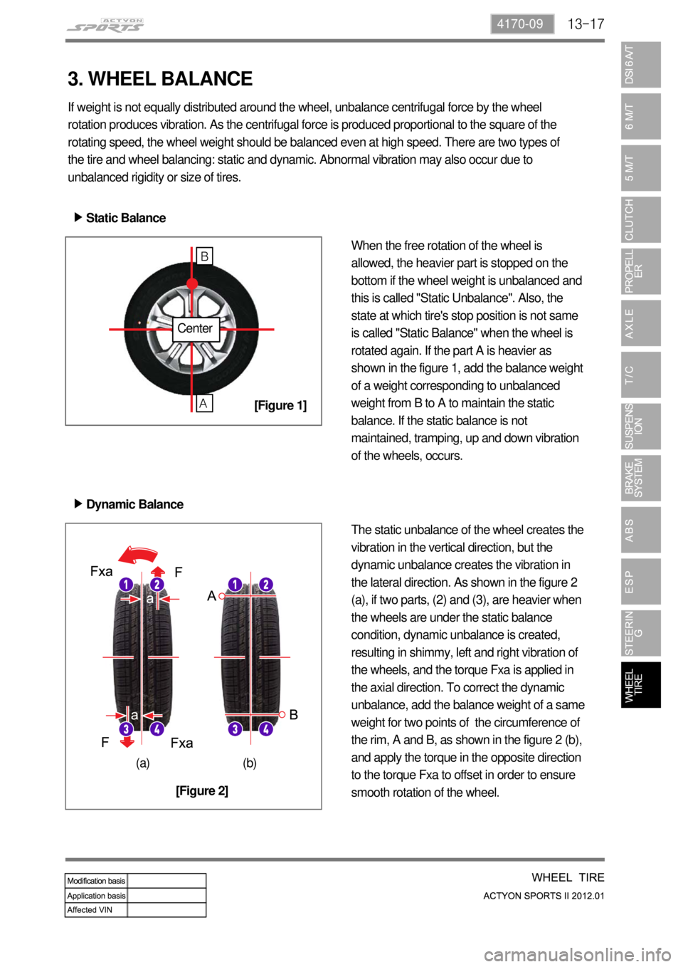
If weight is not equally distributed around the wheel, unbalance centrifugal force by the wheel
rotation produces vibration. As the centrifugal force is produced proportional to the square of the
rotating speed, the wheel weight should be balanced even at high speed. There are two types of
the tire and wheel balancing: static and dynamic. Abnormal vibration may also occur due to
unbalanced rigidity or size of tires.
Static Balance ▶
When the free rotation of the wheel is
allowed, the heavier part is stopped on the
bottom if the wheel weight is unbalanced and
this is called "Static Unbalance". Also, the
state at which tire's stop position is not same
is called "Static Balance" when the wheel is
rotated again. If the part A is heavier as
shown in the figure 1, add the balance weight
of a weight corresponding to unbalanced
weight from B to A to maintain the static
balance. If the static balance is not
maintained, tramping, up and down vibration
of the wheels, occurs.
Dynamic Balance ▶
The static unbalance of the wheel creates the
vibration in the vertical direction, but the
dynamic unbalance creates the vibration in
the lateral direction. As shown in the figure 2
(a), if two parts, (2) and (3), are heavier when
the wheels are under the static balance
condition, dynamic unbalance is created,
resulting in shimmy, left and right vibration of
the wheels, and the torque Fxa is applied in
the axial direction. To correct the dynamic
unbalance, add the balance weight of a same
weight for two points of the circumference of
the rim, A and B, as shown in the figure 2 (b),
and apply the torque in the opposite direction
to the torque Fxa to offset in order to ensure
smooth rotation of the wheel.
Center
A
B
(a) (b)
[Figure 1]
[Figure 2]
3. WHEEL BALANCE
Page 813 of 828
03-16
1) Types of Child Restraint System
There are 2 securing types for the child restraint system.
By using seat belt
By using ISOFIX (for the vehicle with ISOFIX system) -
-
2) Securing the Child Restraint Seat (Normal Baby Seat)
Item Weight AgeFixing
methodRear
left/right seat
Driver seat/rear
center seat
Reversed seat< 10kg 6 to 9 months Seat belt U/SU X
< 13kg 12 to 15 months Seat belt U/SU X
Forward seat
9 to 18kg 9 to 48 monthsSeatbelt/
ISOFIXU/UF/SU X
Booster seat 15 to 25 kg 4 to 6 years Seat belt U X
Booster
cushion22 to 36 kg 6 to 11 years Seat belt U X
U: General child restraint system which should be fixed with the seat belt approved by official
institute.
UF/ SU: General child restraint system which should be fixed with the ISOFIX approved by
official/semiofficial institute.
X: Seat which is not allowed to use child restraint system. -
-
-
Page:
< prev 1-8 9-16 17-24