Page 382 of 828
04-6
2. DESCRIPTION AND OPERATION
1) General Description
The cooling system maintains the engine temperature at an efficient level during all engine
operating conditions.
When the engine is cold, the cooling system cools the engine slowly or not at all. This slow
cooling of the engine allows the engine to warm up quickly.
The cooling system includes a radiator and recovery subsystem, cooling fans, a thermostat and
housing, a water pump, and a water pump drive belt. The timing belt drives the water pump.
All components must function properly for the cooling system to operation. The water pump
draws the coolant from the radiator. The coolant then circulates through water jackets in the
engine block, the intake manifold, and the cylinder head. When the coolant reaches the operating
temperature of the thermostat, the thermostat opens. The coolant then goes back to the radiator
where it cools.
This system directs some coolant through the hoses to the heat core. This provides for heating
and defrosting.
The coolant reservoir is connected to the radiator to recover the coolant displaced by expansion
from the high temperatures. The coolant reservoir maintains the correct coolant level.
The cooling system for this vehicle has no radiator cap or filler neck. The coolant is added to the
cooling system through the coolant reservoir.
2) Radiator
This vehicle has a lightweight tube-and-fin aluminum radiator. Plastic tanks are mounted on the
upper and the lower sides of the radiator core.
On vehicles equipped with automatic transaxles, the transaxle fluid cooler lines run through the
radiator tank.
A radiator drain plug is on this radiator.
To drain the cooling system, open the drain plug.
3) Coolant Reservoir
The coolant reservoir is a transparent plastic reservoir, similar to the windshield washer reservoir.
The coolant reservoir is connected to the radiator by a hose and to the engine cooling system by
another hose.
As the vehicle is driven, the engine coolant heats and expands. The portion of the engine coolant
displaced by this expansion flows from the radiator and the engine into the coolant reservoir. The
air trapped in the radiator and the engine is degassed into the coolant reservoir.
When the engine stops, the engine coolant cools and contracts. The displaced engine coolant is
then drawn back into the radiator and the engine. This keeps the radiator filled with the coolant to
the desired level at all times and increases the cooling efficiency.
Maintain the coolant level between the MIN and MAX marks on the coolant reservoir when the
system is cold.
Page 537 of 828
09-38790-01
1. COMPONENT SPECIFICATIONS
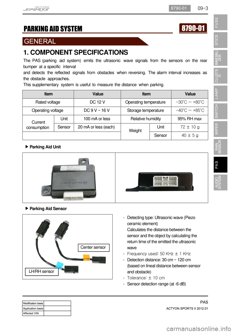
The PAS (parking aid system) emits the ultrasonic wave signals from the sensors on the rear
bumper at a specific interval
and detects the reflected signals from obstacles when reversing. The alarm interval increases as
the obstacle approaches.
This supplementary system is useful to measure the distance when parking.
Parking Aid Unit ▶
Parking Aid Sensor ▶
Detecting type: Ultrasonic wave (Piezo
ceramic element)
Calculates the distance between the
sensor and the object by calculating the
return time of the emitted the ultrasonic
wave
Frequency used: 50 KHz ± 1 KHz
Detection distance: 30 cm ~ 120 cm
(based on lineal distance between sensor
and obstacle)
Tolerance: ± 10 cm
Sensor detection range (at -6 dB) -
-
-
-
-
LH/RH sensor
Center sensor
Item Value Item Value
Rated voltage DC 12 V Operating temperature-30˚C ~ +80˚C
Operating voltage DC 9 V ~ 16 V Storage temperature-40˚C ~ +85˚C
Current
consumptionUnit 100 mA or less Relative humidity 95% RH max
Sensor 20 mA or less (each)
WeightUnit72 ± 10 g
Sensor40 ± 5 g
Page 565 of 828
01-213680-01
Pressure Modulation ▶
To provide a higher level of shift comfort and durability, the hydraulic pressure in the shift related
friction elements of the transmission must be matched accurately to the input torque to
transmission. This hydraulic pressure is composed of a hydraulically pre-set basic pressure and a
control pressure which is set by one of the variable bleed solenoids.
The transmission input torque can be directly calculated from the following operating parameters:
engine torque signals
engine speed or any signal transmitted from ECU through CAN lines
converter slip -
-
-
Separate pressure characteristics for each gear change make it possible to adapt precisely to the
particular shift operation.
5) Shift Mode Selection by TCU
The driver can select Standard (S) or Winter mode (W) with the mode switch. TCU automatically
changes the shift mode according to the transmission oil temperature, uphill or downhill gradient,
and altitude to keep the good driving conditions.
Standard Mode (S) ▶
Uphii and Downhill Mode ▶
Altitude Mode ▶ Standard Mode is selected when setting the mode switch in Standard (S) position with the gear
<009a008c0093008c008a009b00470093008c009d008c0099004700900095004702c8006b02c9004700880095008b0047009b008f008c0047009b009900880095009a00940090009a009a00900096009500470096009000930047009b008c00940097008c00
990088009b009c0099008c0047009000950047009500960099>mal operating range. Proper shift
timing provides the optimized fuel economy and good driving conditions.
In this mode, the operating points of torque converter lock-up clutch and the shifting points are
adjusted according to the vehicle weight.
In this mode, the shifting points are automatically adjusted according to the altitude to compensate
the engine torque changes due to barometric pressure and temperature.
Page 626 of 828
06-2
1. SPECIFICATIONS
Location Front Axle Rear Axle
Type Manual
transmissionAuto
transmissionManual
transmissionAuto
transmission
Torque----
Gear ratio 4.55R 3.91R 4.55R 3.91R
GearType Hypoid←←←
SizeØ182.8 mm ← Ø228.6 mm ←
Offset28.58 mm
(DYMOS)
35 mm (Tongil)←30 mm -
Housing Steel←Steel casting←
OilTypeSAE 80W/90 - GL5
←SAE 80W/90 - GL5
←
Capacity 1.4 L 1.4 LGSL = 1.9 L,
DSL = 2.0 L←
Length 448.0 mm←469.0 mm←
Witdh 681.9 mm←1,717.7 mm←
Weight 45 kg←90 kg←
Page 627 of 828
07-33240-01
1. SPECIFICATIONS
Description Specifications
Type Part-time transfer case
Total length 343 mm
Mating surface of front flange 40 mm
Weight 32.4 kg (including oil)
Oil capacity 1.4 L
Oil type ATF DEXRON III
Location Transfer case
Major element Housing Part-time & TOD
Bolt 11 ea, M8 x 1.25
Input shaft A/T: outer spline
M/T: inner spline
Page 646 of 828
08-10
2. FRONT SUSPENSION (DOUBLE WISHBONE)
Advantage ▶
The advantage of a double wishbone suspension is that it is fairly easy to work out the effect
of moving each joint, so the kinematics of the suspension can be tuned easily and wheel
motion can be optimized.
It is also easy to work out the loads that different parts will be subjected to which allows more
optimized lightweight parts to be designed.
They also provide increasing negative camber gain all the way to full jounce travel unlike the
MacPherson strut which provides negative camber gain only at the beginning of jounce travel
and then reverses into positive camber gain at high jounce amounts. 1.
2.
3.
Disadvantage ▶
The disadvantage is that it is slightly more complex than other systems like a MacPherson strut.
Due to the increased number of components within the suspension setup it takes much longer to
service and is heavier than an equivalent MacPherson design. 1.
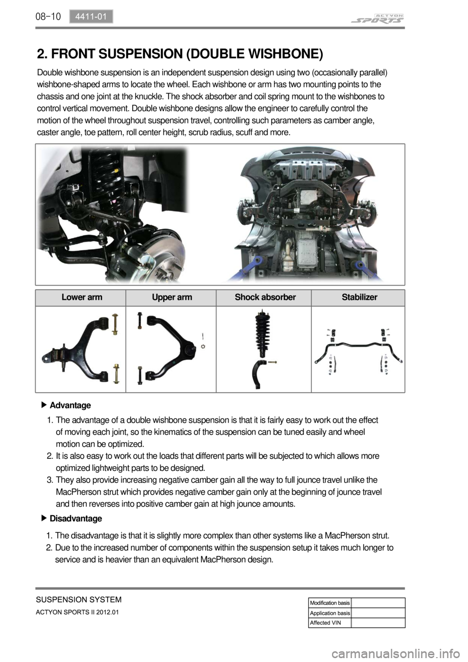
2. Double wishbone suspension is an independent suspension design using two (occasionally parallel)
wishbone-shaped arms to locate the wheel. Each wishbone or arm has two mounting points to the
chassis and one joint at the knuckle. The shock absorber and coil spring mount to the wishbones to
control vertical movement. Double wishbone designs allow the engineer to carefully control the
motion of the wheel throughout suspension travel, controlling such parameters as camber angle,
caster angle, toe pattern, roll center height, scrub radius, scuff and more.
Lower arm Upper arm Shock absorber Stabilizer
Page 647 of 828
08-114411-01
3. REAR SUSPENSION (MULTI LINK TYPE)
Multi-link (5-Link) type suspension is the independent suspension. It provides good ride comfort
and drivability by reducing the coil spring weight. Also, it increases the space for passenger
compartment by lowering the floor. This type of suspension consists of multiple links such as coil
spring, shock absorber, upper and lower arms, lateral rod and stabilizer bar.
Shock absorber Stabilizer bar Rear coil spring
Lower arm Upper arm Lateral rod
Page 693 of 828
10-14
2) Basic Theory of ABS Function
To give you a better understanding of the tasks and functions of ABS, we will first look at the
physics principles.
(1) Stopping distance
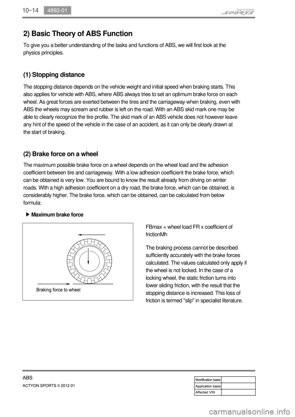
(2) Brake force on a wheel
The maximum possible brake force on a wheel depends on the wheel load and the adhesion
coefficient between tire and carriageway. With a low adhesion coefficient the brake force, which
can be obtained is very low. You are bound to know the result already from driving on winter
roads. With a high adhesion coefficient on a dry road, the brake force, which can be obtained, is
considerably higher. The brake force, which can be obtained, can be calculated from below
formula:
Maximum brake force ▶
FBmax = wheel load FR x coefficient of
frictionMh
The braking process cannot be described
sufficiently accurately with the brake forces
calculated. The values calculated only apply if
the wheel is not locked. In the case of a
locking wheel, the static friction turns into
lower sliding friction, with the result that the
stopping distance is increased. This loss of
friction is termed "slip" in specialist literature.
The stopping distance depends on the vehicle weight and initial speed when braking starts. This
also applies for vehicle with ABS, where ABS always tries to set an optimum brake force on each
wheel. As great forces are exerted between the tires and the carriageway when braking, even with
ABS the wheels may scream and rubber is left on the road. With an ABS skid mark one may be
able to clearly recognize the tire profile. The skid mark of an ABS vehicle does not however leave
any hint of the speed of the vehicle in the case of an accident, as it can only be clearly drawn at
the start of braking.