2012 SSANGYONG NEW ACTYON SPORTS air condition
[x] Cancel search: air conditionPage 329 of 828

15-26
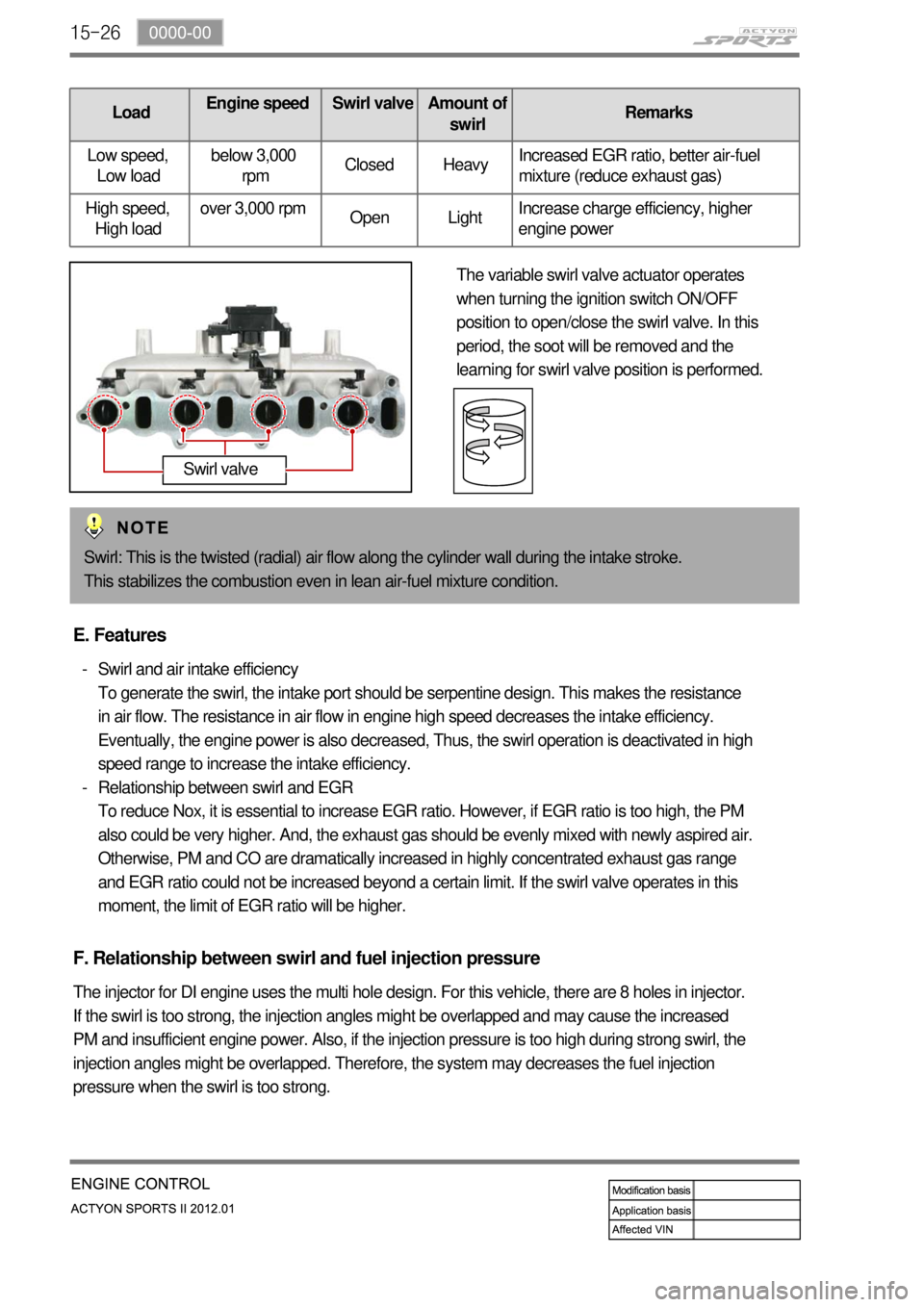
LoadEngine speed Swirl valveAmount of
swirlRemarks
Low speed,
Low loadbelow 3,000
rpmClosed HeavyIncreased EGR ratio, better air-fuel
mixture (reduce exhaust gas)
High speed,
High loadover 3,000 rpm
Open LightIncrease charge efficiency, higher
engine power
The variable swirl valve actuator operates
when turning the ignition switch ON/OFF
position to open/close the swirl valve. In this
period, the soot will be removed and the
learning for swirl valve position is performed.
Swirl: This is the twisted (radial) air flow along the cylinder wall during the intake stroke.
This stabilizes the combustion even in lean air-fuel mixture condition.
Swirl valve
E. Features
Swirl and air intake efficiency
To generate the swirl, the intake port should be serpentine design. This makes the resistance
in air flow. The resistance in air flow in engine high speed decreases the intake efficiency.
Eventually, the engine power is also decreased, Thus, the swirl operation is deactivated in high
speed range to increase the intake efficiency.
Relationship between swirl and EGR
To reduce Nox, it is essential to increase EGR ratio. However, if EGR ratio is too high, the PM
also could be very higher. And, the exhaust gas should be evenly mixed with newly aspired air.
Otherwise, PM and CO are dramatically increased in highly concentrated exhaust gas range
and EGR ratio could not be increased beyond a certain limit. If the swirl valve operates in this
moment, the limit of EGR ratio will be higher. -
-
F. Relationship between swirl and fuel injection pressure
The injector for DI engine uses the multi hole design. For this vehicle, there are 8 holes in injector.
If the swirl is too strong, the injection angles might be overlapped and may cause the increased
PM and insufficient engine power. Also, if the injection pressure is too high during strong swirl, the
injection angles might be overlapped. Therefore, the system may decreases the fuel injection
pressure when the swirl is too strong.
Page 340 of 828

15-370000-00
HFM (intake air
temperature)Cooling fan module
DSI 6 A/T (ATF
temperature)Coolant
temperature senso
r
Refrigerant
pressure sensor
Relay box
(12) Cooling fan control
A. Overview of cooling fan and A/C compressor
The cooling system maintains the engine temperature at an efficient level during all engine
operating conditions. The water pump draws the coolant from the radiator. The coolant then
circulates through water jackets in the engine block, the intake manifold, and the cylinder head.
When the coolant reaches the operating temperature of the thermostat, the thermostat opens.
The coolant then goes back to the radiator where it cools. The heat from automatic transmission
is also cooled down through the radiator by circulating the oil through the oil pump. ECU controls
the electric cooling fans with three cooling fan relays to improve the engine torque and air
conditioning performance.
For detailed information, refer to Chapter "Air Conditioning System".
B. Components
A/C compressor
D20DTR ECU
Page 345 of 828

15-42
D. Control conditions
Operation Operating condition PTC Heater
HI
(PTC2)- Coolant temperature < 15℃PTC HI ON
LO
(PTC1)- Coolant temperature 15℃ ≤ 65℃, intake air
temperature ≤ -10℃
- Coolant temperature 15℃ < 65 to 60℃, intake air
temperature <-10℃ to 0℃
- Coolant temperature 15℃ ≤ 60℃, intake air
temperature ≤ 0℃ to 5℃PTC LO ON
Stop- A/C blower switch OFF
- Defective ambient air temperature sensor
(including open or short circuit)
- Engine cranking
- Low battery voltage (below 11V)
- During pre-glow process (glow indicator ON)
Operation diagram for PTC heater LO (step 2) ▶
Page 360 of 828

01-10
Black Light and Dye Method ▶
A dye and light kit is available for finding leaks, Refer to the manufacturer's directions when using
the kit.
Pour the specified amount of dye into the engine oil fill tube.
Operate the vehicle normal operating conditions as directed in the kit.
Direct the light toward the suspected area. The dyed fluid will appear as a yellow path
leading to the source. -
-
-
Once the origin of the leak has been pinpointed and traced back to its source, the cause of the
leak must be determined in order for it to be repaired properly.
If a gasket is replaced, but the sealing flange is bent, the new gasket will not repair the leak. The
bent flange must be repaired also. Before attempting to repair a leak, check for the following
conditions and correct them as they may cause a leak.Repairing the Leak ▶
Gaskets ▶
The fluid level/pressure is too high.
The crankcase ventilation system is malfunctioning.
The seal bore is damaged (scratched, burred or nicked).
The seal is damaged or worn.
Improper installation is evident.
There are cracks in the components.
The shaft surface is scratched, nicked or damaged.
A loose or worn bearing is causing excess seal wear. -
-
-
-
-
-
-
-
Page 363 of 828

01-131113-01
Leakage Test ▶
Warm the engine up to normal operating temperature.
Disconnect the negative battery cable.
Remove the spark plugs.
Check the coolant level by opening the coolant reservoir cap and replenish if insufficient.
Open the engine oil filler cap.
Connect the tester to air pressure line and adjust the scale of tester.
Install the connecting hose to spark plug hole.
Position the piston of No.1 cylinder at TDC by rotating the crankshaft.
Connect the connecting hose to tester and measure the leakage volume after blowing up
5 bar of compressed air. -
-
-
-
-
-
-
-
-
Measure the leakage volume in the completely opening condition of throttle valve by pulling
the acceleration cable. -
Perform the pressure test according to the firing order. -
Firing Order: 1 - 3 - 4 - 2 -
Compare the leakage pressure with the specifications. -
Page 382 of 828

04-6
2. DESCRIPTION AND OPERATION
1) General Description
The cooling system maintains the engine temperature at an efficient level during all engine
operating conditions.
When the engine is cold, the cooling system cools the engine slowly or not at all. This slow
cooling of the engine allows the engine to warm up quickly.
The cooling system includes a radiator and recovery subsystem, cooling fans, a thermostat and
housing, a water pump, and a water pump drive belt. The timing belt drives the water pump.
All components must function properly for the cooling system to operation. The water pump
draws the coolant from the radiator. The coolant then circulates through water jackets in the
engine block, the intake manifold, and the cylinder head. When the coolant reaches the operating
temperature of the thermostat, the thermostat opens. The coolant then goes back to the radiator
where it cools.
This system directs some coolant through the hoses to the heat core. This provides for heating
and defrosting.
The coolant reservoir is connected to the radiator to recover the coolant displaced by expansion
from the high temperatures. The coolant reservoir maintains the correct coolant level.
The cooling system for this vehicle has no radiator cap or filler neck. The coolant is added to the
cooling system through the coolant reservoir.
2) Radiator
This vehicle has a lightweight tube-and-fin aluminum radiator. Plastic tanks are mounted on the
upper and the lower sides of the radiator core.
On vehicles equipped with automatic transaxles, the transaxle fluid cooler lines run through the
radiator tank.
A radiator drain plug is on this radiator.
To drain the cooling system, open the drain plug.
3) Coolant Reservoir
The coolant reservoir is a transparent plastic reservoir, similar to the windshield washer reservoir.
The coolant reservoir is connected to the radiator by a hose and to the engine cooling system by
another hose.
As the vehicle is driven, the engine coolant heats and expands. The portion of the engine coolant
displaced by this expansion flows from the radiator and the engine into the coolant reservoir. The
air trapped in the radiator and the engine is degassed into the coolant reservoir.
When the engine stops, the engine coolant cools and contracts. The displaced engine coolant is
then drawn back into the radiator and the engine. This keeps the radiator filled with the coolant to
the desired level at all times and increases the cooling efficiency.
Maintain the coolant level between the MIN and MAX marks on the coolant reservoir when the
system is cold.
Page 384 of 828

04-8
The cooling fans are mounted behind the radiator in the engine compartment. The electric cooling
fans increase the flow of air across the radiator fins and across the condenser on air conditioned
(A/C)-equipped vehicles.
This helps to speed cooling when the vehicle is at idle or moving at low speeds.
All models have two fans. The main fan is 320 mm (12. 6 inches) in diameter with seven blades to
aid the airflow through the radiator and the condenser. An electric motor attached to the radiator
support drives the fan.
The auxiliary fan is 320 mm (12.6 inches) in diameter.
A/C Off or Non-AC Model ▶
The cooling fans are actuated by the engine control module (ECM) using a low-speed
cooling fan relay, a high-speed cooling fan relay and a cooling fan motor relay.
The ECM will turn the cooling fans on at low speed when the coolant temperature reaches
95°C(203°F) and at high speed when the coolant temperature reaches 105°C(221°F).
The ECM will change the cooling fans from high peed to low speed at 100°C(212°F) and
will turn the cooling fans off at 90°C (194°F). -
-
-
A/C On ▶
The ECM will turn the cooling fans on at low speed when the A/C system is on. The ECM
will change to high speed when the high side A/C pressure reaches 1860 kPa (269.8 psi).
The cooling fans will return to low speed when the high side A/C pressure reaches 1378
kPa (199.8 psi). -
-
7) Engine Coolant Temperature Sensor
The Engine Coolant Temperature (ECT) sensor uses a temperature to control the signal voltage to
the Engine Control Module (ECM).
8) Coolant Temperature Gauge
The coolant temperature gauge controls the instrument panel temperature indicator. The coolant
temperature gauge is located with ECT sensor.
Page 499 of 828

04-8
No. Symbol ItemBulb
TypePower Turning ON condition
13Engine check
warning lampLED IGN IGN ON/ CAN signal input
144WD LOW
indicatorLED IGN IGN ON/ CAN signal input
15ESP indicator/
warning lightLED IGNIGN ON/ CAN signal input
(ESP & buzzer activated)
16
ESP OFF indicatorLED IGN IGN ON/ CAN signal input
17Brake warning light
LED IGNIGN ON, CAN signal input
(EBD)
184WD CHECK
indicatorLED IGN IGN ON/ CAN signal input
19Air bag warning
lampLED IGN Signal input
20Door ajar waning
lightLED BATT When door opened
21Charge warning
lampLED IGN Charge system fault
22Seat belt warning
lightLED IGN Switch input