Page 141 of 828
02-4
2. TIGHTENING TORQUE
Component SizeBolt
QuantitySpecified torque
(Nm)Remark
(Total torque)
Main bearing capM12×8210 55±5Nm,
180˚Not re-usable
Connecting rod capM9×52840±5Nm,
90˚+10˚50 to 80 Nm
Rear coverM6×20610 ± 1 Nm-
Oil pumpM8×35SOC325 ± 2.5 Nm-
FlywheelM10×22845 ± 5 Nm,
90˚+10˚60 to 100 Nm
Crankshaft center boltM20×851200 ± 20 Nm,
180˚+20˚660 to 720 Nm
Not re-usable
Oil panM6×201810 ± 1 Nm-
M6×35210 ± 1 Nm-
M6×85210 ± 1 Nm-
M6×120210 ± 1 Nm-
M8×40225 ± 2.5 Nm-
HP pump main nutM14×1.5-8-1165 ± 5 Nm-
HP pump boltM8×55325 ± 2.5 Nm-
Cylinder headM13×15012 85Nm
270°±10°-
Camshaft capM6×301610 ± 1 Nm -
M8×60425 ± 2.5 Nm -
Exhaust stud bolt 1015±1.5Nm-
Exhaust sprocket boltM11×40130 ± 3 Nm -
Chain tensioner screw
boltM38×1.5 125±2.5Nm -
Coolant temperature
sensor120±2.0Nm -
Auto tensionerM8×30(LOW) 125±2.5Nm -
M10×75(Upper) 155±5.5Nm -
Coolant pumpM6×50 110±1.0Nm -
Page 148 of 828

02-110000-00
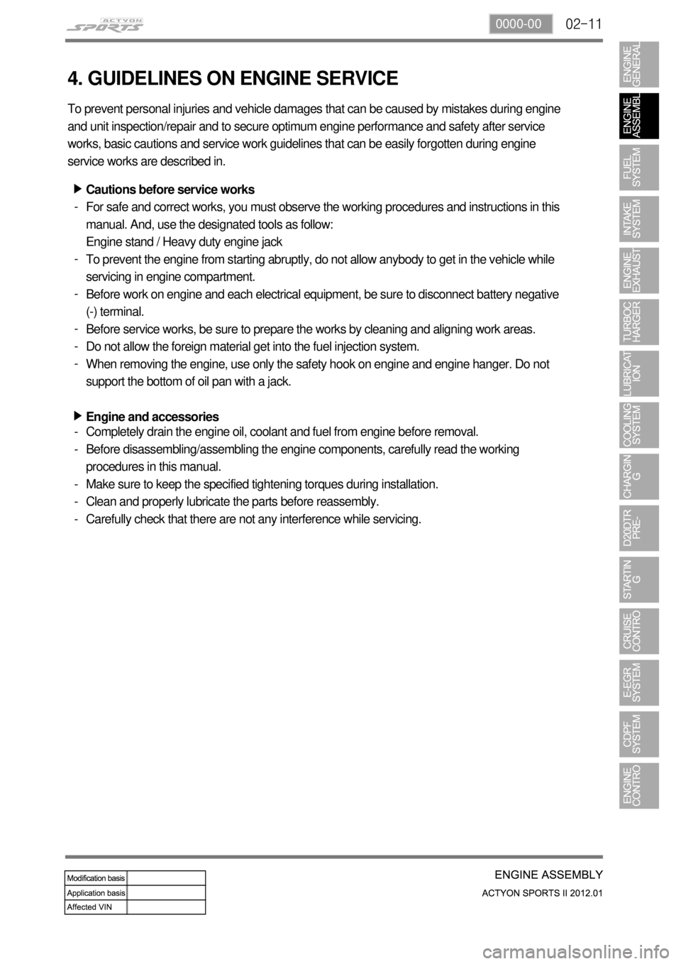
4. GUIDELINES ON ENGINE SERVICE
To prevent personal injuries and vehicle damages that can be caused by mistakes during engine
and unit inspection/repair and to secure optimum engine performance and safety after service
works, basic cautions and service work guidelines that can be easily forgotten during engine
service works are described in.
Cautions before service works
For safe and correct works, you must observe the working procedures and instructions in this
manual. And, use the designated tools as follow:
Engine stand / Heavy duty engine jack
To prevent the engine from starting abruptly, do not allow anybody to get in the vehicle while
servicing in engine compartment.
Before work on engine and each electrical equipment, be sure to disconnect battery negative
(-) terminal.
Before service works, be sure to prepare the works by cleaning and aligning work areas.
Do not allow the foreign material get into the fuel injection system.
When removing the engine, use only the safety hook on engine and engine hanger. Do not
support the bottom of oil pan with a jack.
Engine and accessories ▶
-
-
-
-
-
-
▶
Completely drain the engine oil, coolant and fuel from engine before removal.
Before disassembling/assembling the engine components, carefully read the working
procedures in this manual.
Make sure to keep the specified tightening torques during installation.
Clean and properly lubricate the parts before reassembly.
Carefully check that there are not any interference while servicing. -
-
-
-
-
Page 162 of 828
02-250000-00
Location of Expansion Plugs
1) Cylinder Head
(1) Overview
The cylinder is made by gravity casting and the water jacket is integrated type.
The cylinder oil passage is drilled and sealed by cap.
The Camshaft bearing cap is also made by casting and installed on the cylinder head.
(2) Features
FrontRear
Coolant expansion plug (M21)
Oil gallery expansion plug (M10)
Intake side
Page 185 of 828
02-48
The bottom side of water jacket is desgined as sine wave to strengthen the structure of crankcase.
The main flow of coolant starts from outlet port of water pump and goes along the longitudinal
direction of engine. The coolant passage from cylinder head to inlet port of water pump is
integrated in cylinder head.
The engine oil from oil pump is supplied to the main oil gallery through oil channel, oil filter
module and cross bore in cylinder block without using external pipes. This oil is supplied to main
bearing, cylinder head and MBU. And, it is sprayed to the chain through the chain tensioner
connected to cross bore.
Crankcase cross bore for oil supply
Water jacket core
Page 199 of 828
03-16
Dynamic test for backleak of injector ▶
Warm up the engine so that the engine
coolant temperature be over 80℃ and star
the engine again.
Disconnect the injector return hose and
cover the openings with caps shaped
screw (included in the special tool).. 1.
2.
Connect the hose of the container for
measuring backleak to the return nipple of
the injector.
Start the engine again and let the engine
idle for 30 seconds.
Perform backleak test of fuel system with a
diagnostic device after 30 seconds. 3.
4.
5.
This test consists of 4 cycles, and the engine
rpm reaches 3,500 rpm for 18 seconds in each
cycle.
Check the amount of backleak collected
into the container and confirm that it is
within the specified range. 6.
Specification38 ml or less
Page 209 of 828

03-26
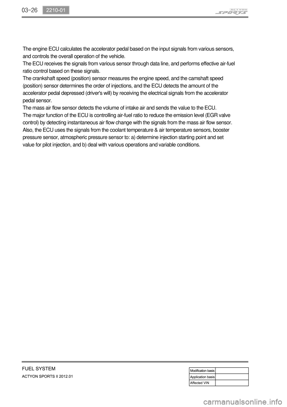
The engine ECU calculates the accelerator pedal based on the input signals from various sensors,
and controls the overall operation of the vehicle.
The ECU receives the signals from various sensor through data line, and performs effective air-fuel
ratio control based on these signals.
The crankshaft speed (position) sensor measures the engine speed, and the camshaft speed
(position) sensor determines the order of injections, and the ECU detects the amount of the
accelerator pedal depressed (driver's will) by receiving the electrical signals from the accelerator
pedal sensor.
The mass air flow sensor detects the volume of intake air and sends the value to the ECU.
The major function of the ECU is controlling air-fuel ratio to reduce the emission level (EGR valve
control) by detecting instantaneous air flow change with the signals from the mass air flow sensor.
Also, the ECU uses the signals from the coolant temperature & air temperature sensors, booster
pressure sensor, atmospheric pressure sensor to: a) determine injection starting point and set
value for pilot injection, and b) deal with various operations and variable conditions.
Page 239 of 828
06-191914-01
T-MAP sensor
Booster pressure and
temperature
E-VGT turbocharger
Improves engine power
2. COMPONENTS
Engine ECU (D20DTR)
E-VGT duty controlAccelerator pedal position
sensor
Transfers driver's will to
accelerate to ECU
Atmospheric pressure, RPM
signal
HFM sensor
Improves the engine powerCoolant temperature sensor
Operates the VGT according
to engine warm-up
* 세부제어로직은 엔진제어편 참조
Page 246 of 828
08-31520-00
1. SPECIFICATION
Unit Description Specification
Cooling system Type Water cooling, forced circulation
Coolant Capacity approx. 8.5 L
Radiator Core size 555W x 582.4H x 27T (over 326,250mm2)
Flow type Cross flow
Min. cooling capacity over 68,000 kcal/h
Antifreeze Type Long life coolant
Mixing ratio
(water:antifreeze)50 : 50
Cooling fan module Type Electric
CapacityØ472 x 400W x 5B
Control type PWM type
Coolant reservoir Capacity over 1.5 L
Circulation Closed roof type
Pressure cap Screw type, 1.4bar
Vacuum valve Screw type, 1.4bar
Thermostat Type Wax pallet type
Opening temperature90˚C
Fully open temperature100˚C
Valve lift 8 mm