Page 965 of 1082

11-130000-00
ESP controls during understeer ▶
The ESP system recognizes the directional angle with the steering wheel angle sensor and senses the
slipping route that occurs reversely against the vehicle cornering direction during understeer with the ya
w
rate sensor and lateral sensor. Then, the ESP system applies the braking force to the rear inner wheel to
compensate the yaw moment value. In this way, the vehicle does not lose its driving direction and the
driver can steer the vehicle as intended.
(2) Over steering
What is oversteering? ▶
Oversteer is a term of a condition in which the steering wheel is steered to a certain angle during driving
and the rear tires slip outward losing traction.
Compared to understeering vehicles, it is hard to control the vehicle during cornering and the vehicle can
spin due to rear wheel moment when the rear tires lose traction and the vehicle speed increases.
ESP controls during oversteer ▶
The ESP system recognizes the directional angle with the steering wheel angle sensor and senses the
slipping route that occurs towards the vehicle cornering direction during oversteer with the yaw rate
sensor and lateral sensor. Then the ESP system applies the braking force to the front outer wheel to
compensate the yaw moment value. In this way, the vehicle does not lose its driving direction and the
driver can steer the vehicle as intended.
Page 968 of 1082

11-16
5) ARP (Active Roll-Over Protection)
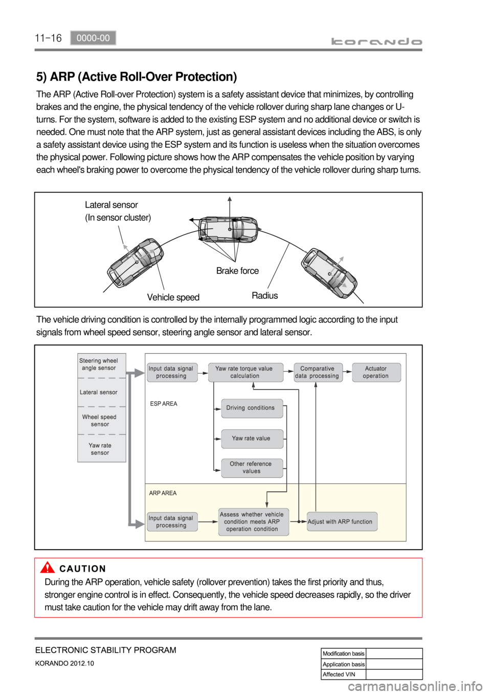
The ARP (Active Roll-over Protection) system is a safety assistant device that minimizes, by controlling
brakes and the engine, the physical tendency of the vehicle rollover during sharp lane changes or U-
turns. For the system, software is added to the existing ESP system and no additional device or switch is
needed. One must note that the ARP system, just as general assistant devices including the ABS, is only
a safety assistant device using the ESP system and its function is useless when the situation overcomes
the physical power. Following picture shows how the ARP compensates the vehicle position by varying
each wheel's braking power to overcome the physical tendency of the vehicle rollover during sharp turns.
Lateral sensor
(In sensor cluster)
Vehicle speedBrake force
Radius
The vehicle driving condition is controlled by the internally programmed logic according to the input
signals from wheel speed sensor, steering angle sensor and lateral sensor.
During the ARP operation, vehicle safety (rollover prevention) takes the first priority and thus,
stronger engine control is in effect. Consequently, the vehicle speed decreases rapidly, so the driver
must take caution for the vehicle may drift away from the lane.
Page 980 of 1082
12-30000-00
1. SPECIFICATION (HPS)
Component Item Specification
Steering wheel Type 3-spoke
Outside diameterΦ 380 mm
Number of revolutions 3.11 rotations
Heated wire Simple ON/OFF
Gear box Type Rack and pinion
Gear ratio 46.94
Rack stroke± 73 mm
Steering angle Inner39°
Outer31.24°
Wheel alignment Toe-in2 ± 2 mm
Oil pump Type Vane (removable pump and reservoir)
Maximum pressure100 ± 3 bar
Displacement6.0 to 9.75 ℓ/min
Pulley diameterΦ 115 mm
Steering column Tilting angle Up + 2.0
Down - 30
Lower shaft Type Ball slip
Steering oil Oil typeATF Dexron Ⅱ or Ⅲ
Oil reservoir capacity1 ℓ
Change interval EU (Diesel): Check and add at every 20,000
km
GEN (Diesel, Gasoline): Check and add at
every 15,000 km
Turning capability Min. turning radius 5.4 m
Page 981 of 1082
12-4
2. TIGHTENING TORQUE
Item Tightening torque Remark
1. Power steering reservoir mounting bolt 8.8 to 13.7 Nm 12 mm x 2 EA
2. Power steering
pumpUpper mounting bolt/nut25 ± 2.5 Nm13 mm x 1 EA
Lower mounting bolt25 ± 2.5 Nm12 mm x 2 EA
3. Oil pipe Eye bolt (pump side) 53.9 to 63.7 Nm 22 mm
Steering gear box side nut 31.4 to 37.2 Nm 17 mm
4. Oil pipe bracket mounting nut 6.8 to 10.8 Nm 10 mm
5. Tie rod end lock nut 44.1 to 53.9 Nm 17 mm
6. Tie rod nut 63.7 to 78.4 Nm 22 mm
7. Lower shaft Lower mounting bolt
(gear box side)17.6 to 24.5 Nm 12 mm
Upper mounting bolt (column
side)17.6 to 24.5 Nm 12 mm
8. Column shaft Lower mounting bolt 19.6 to 24.5 Nm 12 mm
Upper mounting nut 19.6 to 24.5 Nm 12 mm
9. Steering wheel nut 39.2 to 58.8 Nm 22 mm
10. Loosened gear box mounting bolt/nut Left: 98.0 to 127.4 Nm 17 mm
Right: 88.3 to 107.9 Nm 17 mm
11. Heat shield mounting bolt 8.8 to 13.7 Nm 12 mm x 2 EA
Page 983 of 1082
12-6
4. MAJOR CHANGES
1) Steering Heating System
Steering wheel heating unit
Old New
The steering wheel heated wire and the heating unit are
installed in the steering wheel assembly.Lower switch cluster
Old
New
The steering wheel heating switch has
been added on the lower switch cluster.
Specifications ▶
Description Specification
Power consumption Below 95W
Rated voltage 12V
Operating voltage 9V~16V
Rated current6±2.0A
Steering wheel
heating unit
Steering wheel
heating switch
Page 984 of 1082

12-70000-00
1. SYSTEM DESCRIPTION
The power steering has been designed to make the wheel move more easily than in a manual steering
system. The hydraulic power assists the process utilizing hydraulic fluid. The fluid increases pressure in
the power steering pump and aids the movement of the steering mechanism.
The power steering system consists of pump, oil reservoir, rack and gear box.
The power steering pump is a vane type and delivers hydraulic pressure to operate the power steering
system.
The pressure relief valve in the pump controls the discharging pressure.
The rotary valve in the rack and the pinion gear directs the oil from the power steering pump to one side
of the rack piston. The integrated rack piston converts the hydraulic pressure to linear movement. The
operating force of the rack moves the wheels through the tie rod, the tie rod end and the steering knuckle.
Even though the hydraulic pressure cannot be generated, a driver can steer the vehicle without power
assist but it needs very high steering force.
In this case, the operating force of the steering wheel is conveyed to the pinion, and the movement of the
pinion moves the rack through the pinion gear combined to the rack gear.
Page 986 of 1082
13-34610-00
1. SPECIFICATION
Unit Description Specification
System operationOperating type Motor driven power steering system
Operating temperature- 40°C to 80°C
Rated voltage 12 V
Rated current 85 A
Operating voltageNetwork 8 to 16 V
C-EPS ECU 8 to 16 V
Full Performance 10 to 16 V
MotorType 3-Phase BLAC (Brushless AC)
Rated current/voltage 85 A / 12 V (at idle 0.5 A)
Position sensor type Hall sensor type
Torque & angle sensorType Non-contact type
Steering columnOperating type Manual tilting & telescoping
Lower shaftType Sliding (Ball slip) type
Steering gearGear ratio 46.94 mm/rev
Rack stroke 146 mm
Maximum steering angleInner wheel39°
Outer wheel31.24°
Page 989 of 1082

13-6
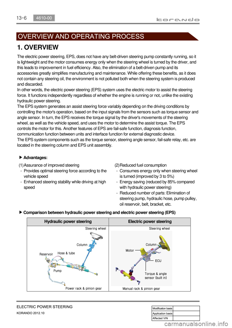
Hydraulic power steering Electric power steering
1. OVERVIEW
The electric power steering, EPS, does not have any belt-driven steering pump constantly running, so it
is lightweight and the motor consumes energy only when the steering wheel is turned by the driver, and
this leads to improvement in fuel efficiency. Also, the elimination of a belt-driven pump and its
accessories greatly simplifies manufacturing and maintenance. While offering these benefits, as it does
not contain any steering oil, the environment is not polluted both when the steering system is produced
and discarded.
In other words, the electric power steering (EPS) system uses the electric motor to assist the steering
force. It functions independently regardless of whether the engine is running or not, unlike the existing
hydraulic power steering.
The EPS system generates an assist steering force variably depending on the driving conditions by
controlling the motor's operation, based on the input signals from the sensors such as torque sensor and
angle sensor. In turn, the EPS receives the torque signal by the driver's movements of the steering
wheel, as well as the vehicle speed, and uses the motor to determine the assist torque. The EPS
controls the motor for this. Another features of EPS are fail-safe function, diagnosis function,
communication function between units and interface function for external diagnostic device.
The EPS system components such as the torque sensor, steering angle sensor, fail-safe relay, etc. are
located in the steering column and EPS unit assembly.
Advantages: ▶
Assurance of improved steering
Provides optimal steering force according to the
vehicle speed
Enhanced steering stability while driving at high
speed (1)
-
-Reduced fuel consumption
Consumes energy only when steering wheel
is turned (improved by 3 to 5%)
Energy saving (reduced by 85% compared
with hydraulic power steering)
Reduced number of parts: Elimination of
steering pump, hydraulic hose, pump pulley,
oil reservoir, belt, bracket, etc. (2)
-
-
-
Comparison between hydraulic power steering and electric power steering (EPS) ▶