Page 106 of 1082

01-10
(4) Fuel and lubrication system
When working with the fuel or oil systems in enclosed area, always keep the working area well-
ventilated and never allow anybody to smoke.
Gaskets and seals on the fuel and oil systems should be replaced with new ones. All bolts and
nuts should be tightened as specified.
Make sure to check the connections for leak after installation. -
-
-
If fine dust or foreign material enters into DI engine's fuel system, there can be serious damages
between HP pump and injectors. So, be sure to cover removed fuel system components with cap
and protect removed parts not to be contaminated with dirt. (Refer to cleanness in this manual
while working on DI engine fuel system)
When working on the fuel line between priming pump and injector (including return line), always
plug the openings with caps to prevent foreign materials or dust from entering to the openings and
connections.
The HP fuel supply pipe (HP pump to fuel rail) and HP fuel pipe (Fuel rail to injector) should be
replaced with new ones when removed. 1.
2.
3.
Page 113 of 1082
02-6
품명 규격 볼트
수량규정토오크(Nm) 비고
(총 토오크)
Oil gauge tubeM6×16110 ± 1Nm-
Oil filter cap 125 ± 2.5Nm-
Fuel railM8×35225 ± 2.5Nm-
Injector clamp boltM6×6029 ± 1.0Nm
130˚ + 10˚-
High pressure pipe
(between HP pump and
fuel rail)M17 130 ± 3Nm
-
High pressure pipe
(between fuel rail and
injector)M17 430 ± 3Nm
-
Crank position sensor
M5×1418 ± 0.4Nm
-
Main wiringM6×16510 ± 1Nm-
Intake duct M8x25 325 ± 2.5Nm-
Power steering pumpM8×100325 ± 2.5Nm-
Mass balance shaft
(MBU)M8×45630 ± 3Nm-
Cylinder head front cove
rM6×10510 ± 1Nm-
품명 규격볼트
수량규정토오크(Nm)비고
(총 토오크)
Timing gear case coverM6×40710 ± 1Nm-
M6×45110 ± 1Nm-
M6×50310 ± 1Nm-
Cylinder head coverM6×352110 ± 1Nm-
Component Size
QuantityTightening torque
(Nm)Remark
(Total torque)
Idle pulley/Tensioner
pulley145 ± 4.5Nm
-
Glow plug M5 420 ± 2Nm-
Vacuum pumpM8×25310 ± 1Nm-
Page 122 of 1082

02-150000-00
Electrical equipment ▶
Electric devices should be handled more carefully.
Currently, the engine has a lot of electric devices. there could be poor engine performance, incomplete
combustion and other abnormal symptoms due to short circuit or poor contact.
Before work on engine and each electrical equipment, be sure to disconnect battery negative (-)
terminal.
When replacing the electric device, use only genuine part and check the conditions of connections
and grounds. Loosened connection or ground make cause a fire and personal injury. -
-Fuel and lubrication system ▶
Do not allow the fluid and engine oil to make contact with the body paintwork and hoses.
If work on the fluid system such as fuel and oil, working area should be well ventilated and smoking
should be prohibited.
Gasket or seal on the fuel/lubrication system should be replaced with new ones and bolts and nuts
should be tightened as specified.
After removal/installation works, be sure to check whether there is leak on the connecting section. -
-
-
-
If fine dust or foreign material enters into DI engine's fuel system, there can be serious damages in HP
pump and injectors. Thus, be sure to plug the inlets of removed fuel line components with cap and
protect removed parts not to be contaminated with dirt. (Refer to cleanness in this manual while working
on DI engine fuel system)
Page 138 of 1082
03-30000-00
1. SPECIFICATION
Description Specification
Fuel Diesel
Fuel filterTypeFuel heater + priming pump + water separator
integrated type
Filter type Changeable filter element type
every 40,000 km
every 45,000 km
Water accumulating capacity 200 cc
Heater capacity 250W 13.5V
Injector System pressure 1800 bar
High pressure fuel
pumpType Eccentric cam/Plunger type
Operating type Gear driven type
Normal operating temperature-40 ~ 125℃
Operating pressure 1800 bar
Operating temperature-30℃ ~ 120℃
Low pressure fuel
pumpType Vane type
Gear ratio (pump/engine) 0.5 : 1
Pressure 6 bar
Fuel tankCapacity 60 L
Material Plastic
Fuel sender Dual sender type
Change intervalEU
GEN
Page 139 of 1082
03-4
2. MAINTENANCE AND INSPECTION
1) Maintenance Procedures for DI Engine Fuel System
Always keep the workshop and lift clean (especially, from dust).
Always keep the tools clean (from oil or foreign materials).
Wear a clean vinyl apron to prevent the fuzz, dust and foreign materials from getting into fuel system.
Wash your hands and do not wear working gloves. 1.
2.
3.
Follow the below procedures before starting service works for fuel system.
If the problem is from HP pump, fuel supply line or injector, prepare the clean special tools and sealing
caps to perform the diagnosis for DI engine fuel system in this manual. At this point, thoroughly clean
the related area in engine compartment. 4.
Clean the engine compartment before starting service works.
Tool kit for high pressure lineTook kit for low pressure line
Page 140 of 1082

03-50000-00
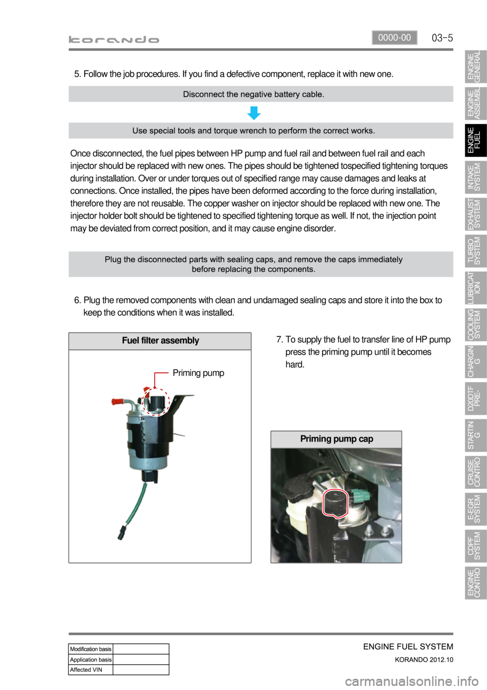
Fuel filter assembly
Follow the job procedures. If you find a defective component, replace it with new one. 5.
Once disconnected, the fuel pipes between HP pump and fuel rail and between fuel rail and each
injector should be replaced with new ones. The pipes should be tightened tospecified tightening torques
during installation. Over or under torques out of specified range may cause damages and leaks at
connections. Once installed, the pipes have been deformed according to the force during installation,
therefore they are not reusable. The copper washer on injector should be replaced with new one. The
injector holder bolt should be tightened to specified tightening torque as well. If not, the injection point
may be deviated from correct position, and it may cause engine disorder.
Plug the removed components with clean and undamaged sealing caps and store it into the box to
keep the conditions when it was installed. 6.
To supply the fuel to transfer line of HP pump
press the priming pump until it becomes
hard. 7.
Priming pump
Priming pump cap
Page 151 of 1082
03-16
Static test for backleak of injector ▶
Disconnect the injector return hose and cover
the openings with caps shaped screw (included
in the special tool). 1.
Connect the hose of the container for
measuring backleak to the return nipple of the
injector.
(prevent air entry to the low pressure line) 2.
Disconnect the IMV connector of the high
pressure pump and then fuel pressure
sensor connector. 3.
The connector of the injector can be easily
contaminated. Always keep it clean.
Crank the engine for 5 seconds.
Check the flow volume of injector backleak. 4.
5.
If the value is out of the specified range,
replace the injector.
Flow volume of injector
backleakbelow 20 cm
Page 152 of 1082
03-170000-00
Dynamic test for backleak of injector ▶
Warm up the engine so that the engine
coolant temperature be over 80℃ and star
the engine again.
Disconnect the injector return hose and cover
the openings with caps shaped screw
(included in the special tool). 1.
2.
Connect the hose of the container for
measuring backleak to the return nipple of
the injector.
Start the engine again and let the engine
idle for 30 seconds.
Perform backleak test of fuel system with a
diagnostic device after 30 seconds. 3.
4.
5.
This test consists of 4 cycles, and the engine rpm
reaches 3,500 rpm for 18 seconds in each cycle.
Check the amount of backleak collected into
the container and confirm that it is within the
specified range. 6.
Specification38 ml or less