2012 SSANGYONG KORANDO brake light
[x] Cancel search: brake lightPage 260 of 1082

12-138530-00
Do not move the shift lever to Neutral position while driving with the cruise control turned on.
Otherwise, it may result in system malfunction or accidents.
Always be prepared to use the brake or accelerator pedal for safe driving while the cruise control
system is running.
The actual speed can be different from the set speed momentarily when driving on a uphill or
downhill. So, it is recommended to disable the cruise control function on a uphill or downhill. hen
driving on a steep hill use the engine brake and foot brake properly to protect the vehicle system
and for a safe driving.
Ensure that the safe distance is maintained and use the brake pedal if needed. 1.
2.
3.
4.
(1) Abnormal Cancellation of the Cruise Control
Sharp acceleration or deceleration
- 50 km/h faster than set speed
- 25 km/h faster than set speed for one minute
- 70 km/h slower than set speed
- 65 km/h slower than set speed for 3 minutes
When the cruise control lever is faulty.
When the brake switch and the brake light switch input signal are implausible. 1.
2.
3.
When the cruise control function is cancelled abnormally or intermittent problems occur, stop the vehicle
and turn off the ignition switch and remove the key to reset the system. After a while, turn on the ignition
switch again to operate the cruise control system.
Page 467 of 1082

12-138530-00
Do not move the shift lever to Neutral position while driving with the cruise control turned on.
Otherwise, it may result in system malfunction or accidents.
Always be prepared to use the brake or accelerator pedal for safe driving while the cruise control
system is running.
The actual speed can be different from the set speed momentarily when driving on a uphill or
downhill. So, it is recommended to disable the cruise control function on a uphill or downhill. hen
driving on a steep hill use the engine brake and foot brake properly to protect the vehicle system
and for a safe driving.
Ensure that the safe distance is maintained and use the brake pedal if needed. 1.
2.
3.
4.
(1) Abnormal Cancellation of the Cruise Control
Sharp acceleration or deceleration
- 50 km/h faster than set speed
- 25 km/h faster than set speed for one minute
- 70 km/h slower than set speed
- 65 km/h slower than set speed for 3 minutes
When the cruise control lever is faulty.
When the brake switch and the brake light switch input signal are implausible. 1.
2.
3.
When the cruise control function is cancelled abnormally or intermittent problems occur, stop the vehicle
and turn off the ignition switch and remove the key to reset the system. After a while, turn on the ignition
switch again to operate the cruise control system.
Page 677 of 1082

05-14
Indicator
(amber)
Brake warning lamp (brake fluid) ▶
ABS warning lamp ▶
Passenger air bag disable indicator ▶
Indicator
(red)
Indicator
(amber)
Indicator
(red)
EPS ▶
Indicator
(amber)
Immobilizer indicator ▶This indicator comes on when the passenger air bag OFF switch is operated.
This indicator comes on the immobilizer (transponder) is not certified.This lamp comes on when the parking brake is applied or the brake fluid
is insufficient.
If this lamp doesn't go off after the parking brake is released, check the
brake fluid level first and then fluid leakage. -
-
This warning light comes on when the ignition switch is turned to ON
and should go out if the system is normal -
This indicator comes on when the EPS system is faulty.
Page 828 of 1082

01-18
A. Indicators on instrument cluster
C. HECU assembly
The HECU assemblies for ABS and ESP have
similar appearance but they have different inner
structure and connector connections from each
other. D. Front brake assembly
The disc brake for 4WD vehicle is the same with
the one for 2WD vehicle.
7. BRAKE SYSTEM AND ESP SYSTEM LAYOUT
B. Master cylinder assembly
Description for master cylinder in this chapter is
based on ABS/ESP equipped vehicle. For CBS,
there is an extra pressure valve mounted to the
master cylinder.
CaliperDisc
Parking brake
warning light
ABS warning lamp
ESP indicator
Page 877 of 1082

03-173660-01
5. TRANSAXLE ELECTRONIC CONTROL SYSTEM
1) General Information
The transmission control unit (TCU) and its input/output network control the following transmission
operations:
Shift timing
Line pressure
Clutch pressure (shift feel)
Torque converter clutch -
-
-
-
also uses these signals when determining transaxle operating strategy. Using all of these input signals,
the TCU can determine when the time and conditions are right for a shift, or when to apply or release the
torque converter clutch. It will also determine the pressure needed to optimise shift feel.
2) TCU (Transmission Control Unit)
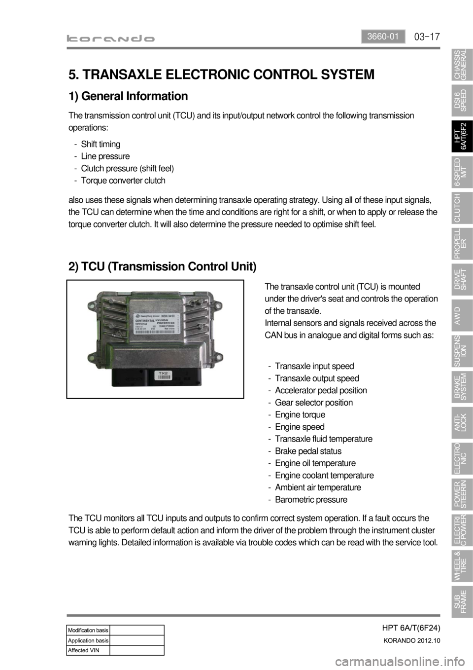
The transaxle control unit (TCU) is mounted
under the driver's seat and controls the operation
of the transaxle.
Internal sensors and signals received across the
CAN bus in analogue and digital forms such as:
Transaxle input speed
Transaxle output speed
Accelerator pedal position
Gear selector position
Engine torque
Engine speed
Transaxle fluid temperature
Brake pedal status
Engine oil temperature
Engine coolant temperature
Ambient air temperature
Barometric pressure -
-
-
-
-
-
-
-
-
-
-
-
The TCU monitors all TCU inputs and outputs to confirm correct system operation. If a fault occurs the
TCU is able to perform default action and inform the driver of the problem through the instrument cluster
warning lights. Detailed information is available via trouble codes which can be read with the service tool.
Page 992 of 1082

14-4
1. OVERVIEW
A radial tire uses a cord angle of 90 degrees. That is, the cord material runs in a radial or direct line from
one bead to the other across the tread. In addition, a radial tire has a belt overwrap under the tread
surface to provide greater structural stability. The belt overwrap of a radial tire distortion while the radial
structure enables high speed driving.
Tire supports the weight of the vehicle, reduces the impact from the road and at the same time,
transmits the power to propel, brake and steer on the road. It also functions to maintain a
<009d008c008f0090008a0093008c02c5009a004700940096009d008c0094008c0095009b0055004700700095004700960099008b008c00990047009b00960047008a0096009400970093008c009b008c0047009a009c008a008f0047009b0088009a009200
9a0053004700880047009b00900099008c00470094009c009a>t be structured to be a resilient
vessel of air.
There is wear limit mark on the tire, which protrudes as a strip shape located approximately 1.6 mm from
<009b008f008c0047008e009900960096009d008c004700890096009b009b0096009400550047007b008f0090009a0047009e008c0088009900470093009000940090009b0047009400880099009200470090009a004700950096009b0047009a008c008c00
950047008d0099009600940047009b008f008c00470096009c>tside so there is additional "▲"
mark on the shoulder to let the driver find the wear mark easily. To measure the tire groove depth,
measure at any point other than the point which has a wear limit mark.
The tire is worn unevenly according to the driver's driving habit, improper servicing, low tire inflation
pressure, changed tire location, etc.
1) Structure of Tire
Tread
This thick layer of rubber provides the interface
between the tire and the road. Wear-resistant
rubber is used to protect the carcass and belt
against fractures and impacts and to deliver a
long driving life.
Shoulder
Located between the tread and sidewall, the
shoulder rubber is the thickest so that the design
must allow for the easy diffusion of heat
generated within the tire while driving.
Sidewall
The part between the shoulder and bead, the
flexible sidewall protects the carcass and
enhances the ride. A tire’s type, size,
structure, pattern, manufacturing company,
product name and various characters are
indicated here. Bead
The bead attaches the tire to the rim and wraps
the end of the cord fabric. Comprised of the bead
wire, core, flipper and other parts, the bead is
generally designed to be slightly tight around the
rim so that in the case of a sudden drop in inflation
pressure, the tire will not fall off the rim.
Carcass
As the most important framework of a tire, the
entire inner layer of cord fabric is called the
carcass. The carcass acts to support air pressure,
vertical load and absorb shocks.
Valve
Belt
Bead core