Page 911 of 1082

06-54110-01
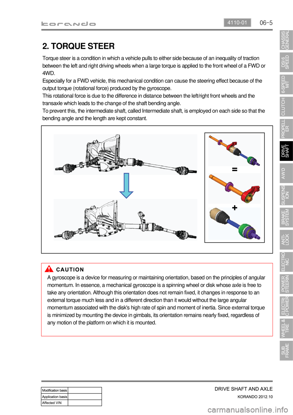
2. TORQUE STEER
Torque steer is a condition in which a vehicle pulls to either side because of an inequality of traction
between the left and right driving wheels when a large torque is applied to the front wheel of a FWD or
4WD.
Especially for a FWD vehicle, this mechanical condition can cause the steering effect because of the
output torque (rotational force) produced by the gyroscope.
This rotational force is due to the difference in distance between the left/right front wheels and the
transaxle which leads to the change of the shaft bending angle.
To prevent this, the intermediate shaft, called Intermediate shaft, is employed on each side so that the
bending angle and the length are kept constant.
A gyroscope is a device for measuring or maintaining orientation, based on the principles of angular
momentum. In essence, a mechanical gyroscope is a spinning wheel or disk whose axle is free to
take any orientation. Although this orientation does not remain fixed, it changes in response to an
external torque much less and in a different direction than it would without the large angular
momentum associated with the disk's high rate of spin and moment of inertia. Since external torque
is minimized by mounting the device in gimbals, its orientation remains nearly fixed, regardless of
any motion of the platform on which it is mounted.
Page 915 of 1082
07-50000-00
2. SYSTEM LAYOUT
1) Components
(1) PTU (Power Transfer Unit)
<007b008f008c004700970096009e008c00990047009b009900880095009a008d008c00990047009c00950090009b0047009000950047009b008f008c0047008d009900960095009b0047009e008f008c008c00930047008b00990090009d008c0047009400
96008b008c00930047008a008f00880095008e008c009a0047>the angle of engine torque to 90°
and transfer it to E-coupling to distribute the torque to rear wheels.
(2) E-Coupling (Electronic Coupling)
E-Coupling transfer the engine torque from PTU to rear axle and controls to distribute it between front
wheels and rear wheels.
(3) E-Coupling Control Unit (ECU)
E-Coupling controls the current (clutch engagement force) of EMCD in E-Coupling according to CAN
signals (wheel speed, engine torque, pedal position, ABS/ESP signals).
* EMCD: Electro-Magnetic Control Device PTU assemblyE-coupling control unit
(located on the floor under driver seat)E-coupling
Page 929 of 1082
09-94850-00
Rear disc brake ▶
Caliper
Brake hose
Brake disc
KnuckleWheel disc
Brake hub
Brake disc
Fastener Tightening torque Remark
Brake pad guide bolt 25.5 ~ 30.4Nm 14 mm x 2EA
Brake caliper mounting bolt 52.9 ~ 63.7Nm 17 mm x 2EA
Brake hose bolt 19.6 ~ 29.4Nm 12mm
Brake hose bracket mounting bolt 9.8 ~ 12.8Nm 12mm
Air breather screw 8.8 ~ 10.8Nm -
1) Tightening torque
Page 955 of 1082
11-30000-00
1. SPECIFICATION
1) Specification of Active Wheel Sensor
Description Specification
Supplying voltage DC 12 V
Output current (at 2.75 km/h of vehicle speed) 7 mA (Lo) ~ 14 mA (Hi) +20%/-16%
Tightening torque Front: 7.8 to 11.8 Nm
Rear: 7.8 to 11.8 Nm
Operating temperature-40 ~ 150 ℃
Operating frequency 1 ~ 2,500 Hz
UnitDescription
ABS ESP
HECU Clock frequency: 32 MHz Clock frequency: 50 MHz
Memory: 128 KB Memory: 512 KB
Switch orifice Switch orifice
Wheel speed sensor Active type Active type
Steering wheel angle
sensorNone Max. detection angle speed:
1500 °/Sec
Operating voltage: 9 to 12 V
Sensor cluster None Yaw rate sensor + lateral G sensor +
longitudinal G sensor (4WD)
Longitudinal G sensor 4WD only None
Pressure sensor None HECU integrated
Page 981 of 1082
12-4
2. TIGHTENING TORQUE
Item Tightening torque Remark
1. Power steering reservoir mounting bolt 8.8 to 13.7 Nm 12 mm x 2 EA
2. Power steering
pumpUpper mounting bolt/nut25 ± 2.5 Nm13 mm x 1 EA
Lower mounting bolt25 ± 2.5 Nm12 mm x 2 EA
3. Oil pipe Eye bolt (pump side) 53.9 to 63.7 Nm 22 mm
Steering gear box side nut 31.4 to 37.2 Nm 17 mm
4. Oil pipe bracket mounting nut 6.8 to 10.8 Nm 10 mm
5. Tie rod end lock nut 44.1 to 53.9 Nm 17 mm
6. Tie rod nut 63.7 to 78.4 Nm 22 mm
7. Lower shaft Lower mounting bolt
(gear box side)17.6 to 24.5 Nm 12 mm
Upper mounting bolt (column
side)17.6 to 24.5 Nm 12 mm
8. Column shaft Lower mounting bolt 19.6 to 24.5 Nm 12 mm
Upper mounting nut 19.6 to 24.5 Nm 12 mm
9. Steering wheel nut 39.2 to 58.8 Nm 22 mm
10. Loosened gear box mounting bolt/nut Left: 98.0 to 127.4 Nm 17 mm
Right: 88.3 to 107.9 Nm 17 mm
11. Heat shield mounting bolt 8.8 to 13.7 Nm 12 mm x 2 EA
Page 986 of 1082
13-34610-00
1. SPECIFICATION
Unit Description Specification
System operationOperating type Motor driven power steering system
Operating temperature- 40°C to 80°C
Rated voltage 12 V
Rated current 85 A
Operating voltageNetwork 8 to 16 V
C-EPS ECU 8 to 16 V
Full Performance 10 to 16 V
MotorType 3-Phase BLAC (Brushless AC)
Rated current/voltage 85 A / 12 V (at idle 0.5 A)
Position sensor type Hall sensor type
Torque & angle sensorType Non-contact type
Steering columnOperating type Manual tilting & telescoping
Lower shaftType Sliding (Ball slip) type
Steering gearGear ratio 46.94 mm/rev
Rack stroke 146 mm
Maximum steering angleInner wheel39°
Outer wheel31.24°
Page 989 of 1082

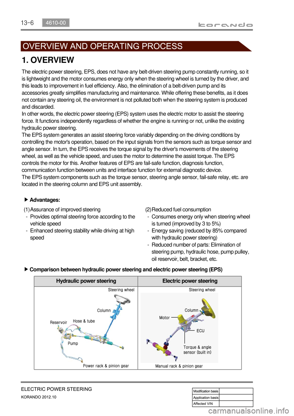
13-6
Hydraulic power steering Electric power steering
1. OVERVIEW
The electric power steering, EPS, does not have any belt-driven steering pump constantly running, so it
is lightweight and the motor consumes energy only when the steering wheel is turned by the driver, and
this leads to improvement in fuel efficiency. Also, the elimination of a belt-driven pump and its
accessories greatly simplifies manufacturing and maintenance. While offering these benefits, as it does
not contain any steering oil, the environment is not polluted both when the steering system is produced
and discarded.
In other words, the electric power steering (EPS) system uses the electric motor to assist the steering
force. It functions independently regardless of whether the engine is running or not, unlike the existing
hydraulic power steering.
The EPS system generates an assist steering force variably depending on the driving conditions by
controlling the motor's operation, based on the input signals from the sensors such as torque sensor and
angle sensor. In turn, the EPS receives the torque signal by the driver's movements of the steering
wheel, as well as the vehicle speed, and uses the motor to determine the assist torque. The EPS
controls the motor for this. Another features of EPS are fail-safe function, diagnosis function,
communication function between units and interface function for external diagnostic device.
The EPS system components such as the torque sensor, steering angle sensor, fail-safe relay, etc. are
located in the steering column and EPS unit assembly.
Advantages: ▶
Assurance of improved steering
Provides optimal steering force according to the
vehicle speed
Enhanced steering stability while driving at high
speed (1)
-
-Reduced fuel consumption
Consumes energy only when steering wheel
is turned (improved by 3 to 5%)
Energy saving (reduced by 85% compared
with hydraulic power steering)
Reduced number of parts: Elimination of
steering pump, hydraulic hose, pump pulley,
oil reservoir, belt, bracket, etc. (2)
-
-
-
Comparison between hydraulic power steering and electric power steering (EPS) ▶
Page 990 of 1082
13-74610-00
2. OPERATION
When the driver turns the steering wheel, a torque is generated and the torque sensor and the steering
angle sensor in the EPS system detect the rotation of the steering column to run the electric motor. At
this time, the worm gear connected to the motor drives the helical gear mounted to the steering column
to generate the assist torque for the steering column. This allows the driver to operate the steering wheel
easier.Output torque = 1) Steering force (manual torque) + 2) Assist torque