2012 SSANGYONG KORANDO Brake
[x] Cancel search: BrakePage 256 of 1082
12-98530-00
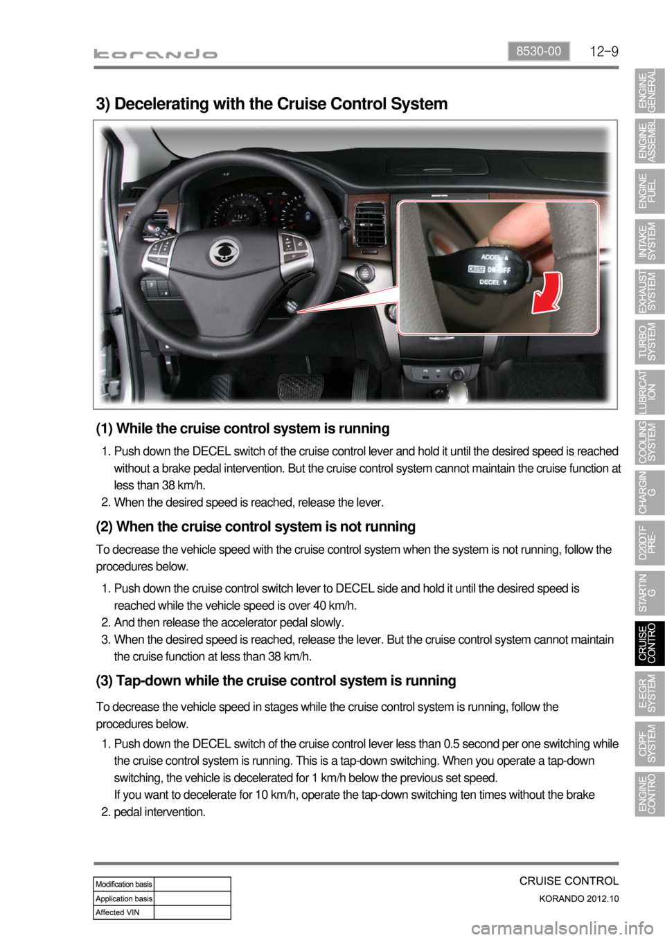
3) Decelerating with the Cruise Control System
(1) While the cruise control system is running
Push down the DECEL switch of the cruise control lever and hold it until the desired speed is reached
without a brake pedal intervention. But the cruise control system cannot maintain the cruise function at
less than 38 km/h.
When the desired speed is reached, release the lever. 1.
2.
(2) When the cruise control system is not running
To decrease the vehicle speed with the cruise control system when the system is not running, follow the
procedures below.
Push down the cruise control switch lever to DECEL side and hold it until the desired speed is
reached while the vehicle speed is over 40 km/h.
And then release the accelerator pedal slowly.
When the desired speed is reached, release the lever. But the cruise control system cannot maintain
the cruise function at less than 38 km/h. 1.
2.
3.
(3) Tap-down while the cruise control system is running
To decrease the vehicle speed in stages while the cruise control system is running, follow the
procedures below.
Push down the DECEL switch of the cruise control lever less than 0.5 second per one switching while
the cruise control system is running. This is a tap-down switching. When you operate a tap-down
switching, the vehicle is decelerated for 1 km/h below the previous set speed.
If you want to decelerate for 10 km/h, operate the tap-down switching ten times without the brake
pedal intervention. 1.
2.
Page 257 of 1082

12-10
4) Recovery of Set Speed (RESUME)
Even if the cruise control is cancelled, the previous set cruise speed can be recovered by pulling up the
cruise control lever when the current vehicle speed is over 38 km/h without an acceleration intervention.
But if you turn off the ignition switch, the memorized set speed is cleared and you cannot recover the
previous set speed.
But the driver should know the previous set speed to react to the changed vehicle speed properly. If
the vehicle speed increases abruptly, depress the brake pedal to adjust the vehicle speed properly.
Page 259 of 1082
12-12
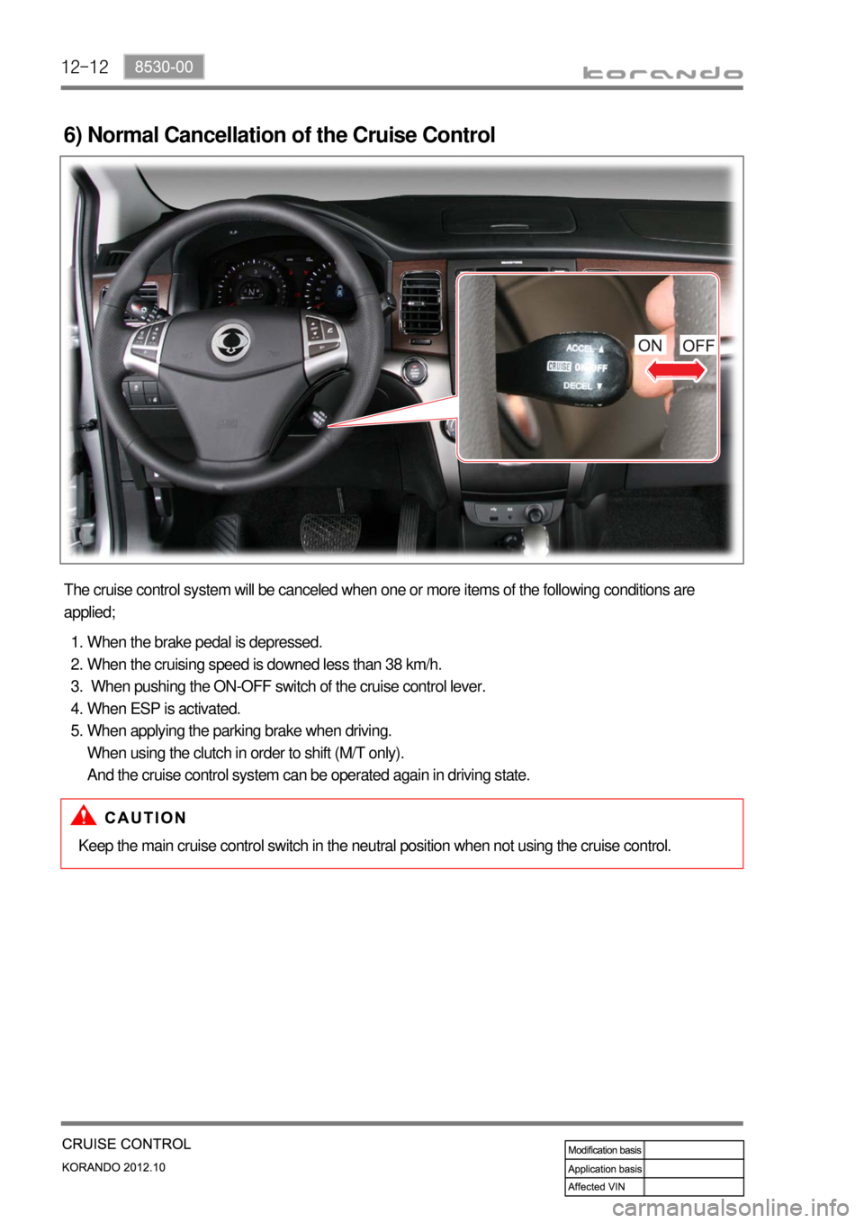
6) Normal Cancellation of the Cruise Control
The cruise control system will be canceled when one or more items of the following conditions are
applied;
When the brake pedal is depressed.
When the cruising speed is downed less than 38 km/h.
When pushing the ON-OFF switch of the cruise control lever.
When ESP is activated.
When applying the parking brake when driving.
When using the clutch in order to shift (M/T only).
And the cruise control system can be operated again in driving state. 1.
2.
3.
4.
5.
Keep the main cruise control switch in the neutral position when not using the cruise control.
Page 260 of 1082
12-138530-00
Do not move the shift lever to Neutral position while driving with the cruise control turned on.
Otherwise, it may result in system malfunction or accidents.
Always be prepared to use the brake or accelerator pedal for safe driving while the cruise control
system is running.
The actual speed can be different from the set speed momentarily when driving on a uphill or
downhill. So, it is recommended to disable the cruise control function on a uphill or downhill. hen
driving on a steep hill use the engine brake and foot brake properly to protect the vehicle system
and for a safe driving.
Ensure that the safe distance is maintained and use the brake pedal if needed. 1.
2.
3.
4.
(1) Abnormal Cancellation of the Cruise Control
Sharp acceleration or deceleration
- 50 km/h faster than set speed
- 25 km/h faster than set speed for one minute
- 70 km/h slower than set speed
- 65 km/h slower than set speed for 3 minutes
When the cruise control lever is faulty.
When the brake switch and the brake light switch input signal are implausible. 1.
2.
3.
When the cruise control function is cancelled abnormally or intermittent problems occur, stop the vehicle
and turn off the ignition switch and remove the key to reset the system. After a while, turn on the ignition
switch again to operate the cruise control system.
Page 279 of 1082

15-30000-00
1. ENGINE DATA LIST
Data Unit Value
Coolant temperature℃ 0.436 V (130℃) to 4.896 V (-40℃)
Intake air temperature℃ -40 to 130℃ (varies by ambient air
temperature or engine mode)
Idle speed rpmA/T780 ± 20
M/T750 ± 20
Engine load % 18~25%
Mass air flow kg/h 16 to 25 kg/h
Throttle position angle°TA 0° (Full Open) to 78° (Close)
Engine torque Nm varies by engine conditions
Injection time ms 3 to 5ms
Battery voltage V 13.5 V to 14.1 V
Accelerator pedal position 1 V 04. to 4.8V
Accelerator pedal position 2 V 0.2 to 2.4 V
Throttle position 1 V 0.3 to 4.6 V
Throttle position 2 V 0.3 to 4.6 V
Oxygen sensor mV 0 to 5 V
A/C compressor switch 1=ON / 0=OFF -
Full load 1=ON / 0=OFF -
Gear selection (A/T) 1=ON / 0=OFF -
Knocking control 1=ON / 0=OFF -
Brake switch 1=ON / 0=OFF -
Cruise control 1=ON / 0=OFF -
Page 283 of 1082

15-70000-00
Fuel rail
pres.sensor
Differential
pressure
sensor
Swirl valve posi.
sensor
Meter cluster
Coolant temp.
sensorE-EGR valve
posi. sensor
Oxygen
sensor
Exhaust gas
temp. sensor
HFM sensor
(2) Components for ECU Input
Crankshaft posi.
sensorAccel. pedal
posi. sensorThrottle
posi.sensor
Knock sensor
T-MAP sensor
Camshaft posi.
sensor
CAN
- ABS&ESP
- GCU
- Meter cluster
- TCU
- BCM
- Refrigerant pressure sensor
- Clutch pedal signal
- Blower switch signal
- Brake pedal signal
Oil level sensor
Page 285 of 1082
15-90000-00
2) ECU Control
(1) Function
a. ECU Function
ECU receives and analyzes signals from various sensors and then modifies those signals into
permissible voltage levels and analyzes to control respective actuators.
ECU microprocessor calculates injection period and injection timing proper for engine piston speed and
crankshaft angle based on input data and stored specific map to control the engine power and emission
gas.
Output signal of the ECU microprocessor drives pressure control valve to control the rail pressure and
activates injector solenoid valve to control the fuel injection period and injection timing; so controls
various actuators in response to engine changes. Auxiliary function of ECU has adopted to reduce
emission gas, improve fuel economy and enhance safety, comforts and conveniences. For example,
there are EGR, booster pressure control, autocruise (export only) and immobilizer and adopted CAN
communication to exchange data among electrical systems (automatic T/M and brake system) in the
vehicle fluently. And Scanner can be used to diagnose vehicle status and defectives.
<00760097008c00990088009b00900095008e0047009b008c00940097008c00990088009b009c0099008c0047009900880095008e008c00470096008d0047006c006a007c00470090009a0047009500960099009400880093009300a000470054005b005700
47009b009600470052005f005c00b6006a004700880095008b> protected from factors like oil,
water and electromagnetism and there should be no mechanical shocks.
To control the fuel volume precisely under repeated injections, high current should be applied instantly
so there is injector drive circuit in the ECU to generate necessary current during injector drive stages.
Current control circuit divides current applying time (injection time) into full-in-current-phase and hold-
current-phase and then the injectors should work very correctly under every working condition.
b. Control Function
Controls by operating stages
To make optimum combustion under every operating stage, ECU should calculate proper injection
volume in each stage by considering various factors.
Starting injection volume control
During initial starting, injecting fuel volume will be calculated by function of temperature and engine
cranking speed. Starting injection continues from when the ignition switch is turned to ignition
position to till the engine reaches to allowable minimum speed.
Driving mode control
If the vehicle runs normally, fuel injection volume will be calculated by accelerator pedal travel and
engine rpm and the drive map will be used to match the drivers inputs with optimum engine power. -
-
-
Page 288 of 1082
15-12
Pilot injection timing control ▶
The pilot injection timing is determined as a function of the engine speed and of the total flow.
The elements are:
A first correction is made according to the air and coolant temperatures. This correction allows the
pilot injection timing to be adapted to the operating temperature of the engine.
A second correction is made according to the atmospheric pressure. This correction is used to adapt
the pilot injection timing as a function of the atmospheric pressure and therefore the altitude. -
-
d. Fuel Control
1. Main Flow Control
The main flow represents the amount of fuel injected into the cylinder during the main injection. The pilot
flow represents the amount of fuel injected during the pilot injection.
The total fuel injected during 1 cycle (main flow + pilot flow) is determined in the following manner.
When the driver depress the pedal, it is his demand which is taken into account by the system in order
to determine the fuel injected.
When the driver release the pedal, the idle speed controller takes over to determine the minimum fuel
which must be injected into the cylinder to prevent the enigne from stalling. ▶
▶
It is therefore the greater of these 2 values which is retained by the system. This value is then compared
with the lower flow limit determined by the ESP system.
As soon as the injected fuel becomes lower than the flow limit determined by the ESP system, the
antagonistic torque (engine brake) transmitted to the drive wheels exceeds the adherence capacity of
the vehicle and there is therefore a risk of the drive wheels locking.
The system thus chooses the greater of these 2 values (main flow & pilot flow) in order to prevent any
loss of control of the vehicle during a sharp deceleration.
As soon as the injected fuel becomes higher than the fuel limit determined by the ASR trajectory control
system, the engine torque transmitted to the wheels exceeds the adhesion capacity of the vehicle and
there is a risk of the drive wheels skidding. The system therefore chooses the smaller of the two values
in order to avoid any loss of control of the vehicle during accelerations.
The anti-oscillation strategy makes it possible to compensate for fluctuations in engine speed during
transient conditions. This strategy leads to a fuel correction which is added to the total fuel of each
cylinder.
The main fuel is obtained by subtracting the pilot injection fuel from the total fuel.
A mapping determines the minimum fuel which can control an injector as a function of the rail pressure.
As soon as the main fuel falls below this value, the fuel demand changes to 0 because in any case the
injector is not capable of injecting the quantity demand. A switch makes it possible to change over from the supercharge fuel to the total fuel according to the
state of the engine.
Until the stating phase has finished, the system uses the supercharged fuel.
Once the engine changes to normal operation, the system uses the total fuel. -
-