2012 MERCEDES-BENZ SLK ROADSTER towing
[x] Cancel search: towingPage 246 of 321
Operating the mobile phone
You can operate the telephon
eusing the
6 and~ buttons on the multifunction
steering wheel. You can operate other mobile
phone functions via the on-board computer
(Y page 187).
When you remove the key from the ignition
lock, the mobile phone stays switched on.
However, you can no longer use the hands-
free system.
If you have an active call and would like to
take the key out of the ignition lock, first
remove the mobile phone from the bracket.
Otherwise, the call is ended.
i When using a bracket connected to the
mobile phone via Bluetooth ®
:ify ou wish to
continue a call in private mode, you will
need to perform the necessary steps on the
mobile phone. Information can be found in
the separate mobile phone operating
instructions. Garage door opener
Important safety notes The HomeLink
®
garage door opener integra-
ted in the rear-view mirror allows you to oper-
ate up to three different door and gate sys-
tems.
i The garage door opener is only available
for certain countries. Observe the legal
requirements for each individual country.
The HomeLink ®
garage door opener is
compatible with most European garage and
gate opener drives. More information on
HomeLink ®
and/or compatible products is
available from:
R any Mercedes-Benz Service Centre
R the HomeLink ®
hotline
(0) 08000 466 354 65 (free of charge) or
+49 (0) 6838 907 277 (charges apply)
R on the Internet at:
http://www.homelink.com Programming the integrated garage
door opener in the rear-view mirror Programming
G
WARNING
Only press the button on the integrated
garage door opener if there are no persons or
objects present within the sweep of the
garage door. Persons could otherwise be
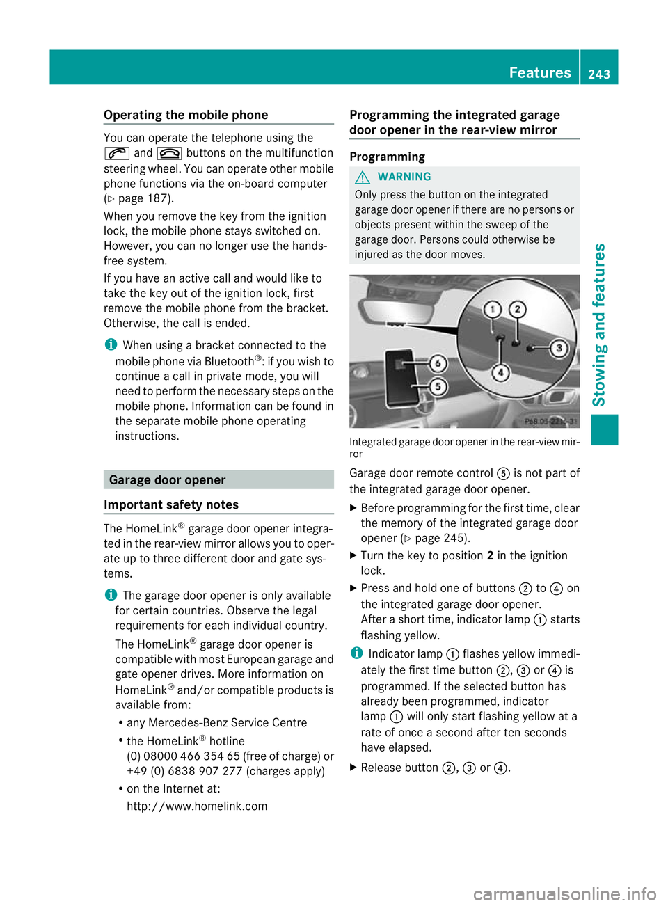
injured as the door moves. Integrated garage door opener in the rear-view mir-
ror
Garage door remote control
Ais not part of
the integrated garage door opener.
X Before programming for the first time, clear
the memory of the integrated garage door
opener (Y page 245).
X Turn the key to position 2in the ignition
lock.
X Press and hold one of buttons ;to? on
the integrated garage door opener.
After a short time, indicator lamp :starts
flashing yellow.
i Indicator lamp :flashes yellow immedi-
ately the first time button ;,=or? is
programmed. If the selected button has
already been programmed, indicator
lamp :will only start flashing yellow at a
rate of once a second after ten seconds
have elapsed.
X Release button ;,=or?. Features
243Stowing and features Z
Page 247 of 321
X
Point garage door remote control A
towards buttons ;to? on the rear-view
mirror at a distance of 5 to 20 cm.
i The required distance between remote
control Aand the integrated garage door
opener depends on the garage door drive
system. You might require several
attempts. You should test every position for
at least 25 seconds before trying another
position.
X Press and hold button Bon remot econtrol
A until indicator lamp :lights up green.
If indicator lamp :lights up green or
flashes, then programming has been suc-
cessful.
X Release button ;,=or? on the inte-
grated garage door opener and button B
on garage door remote control A.
If indicator lamp :lights up red:
X Repeat the programming procedure for the
corresponding button on the rear-view mir-
ror. When doing so, vary the distance
between remote control Aand the rear-
view mirror.
i If the indicator lamp flashes green after
successful programming, the garage door
system is using a rolling code. After pro-
gramming, you must synchronise the
garage door opener integrated in the rear-
view mirror with the receiver of the garage
door system.
Synchronising the rolling code
Your vehicle must be within reach of the
garage door or exterior gate drive. Make sure
that neither your vehicle nor any persons/
objects are present within the sweep of the
door or gate.
Observe the safety notes when performing
the rolling code synchronisation
(Y page 243). X
Turn the key to position 2in the ignition
lock.
X Press the programming button of the door
or gate drive (see the door or gate drive
operating instructions, e.g. under "Pro-
gramming of additional remote controls").
i Usually, you now have 30seconds to ini-
tiate the next step.
X Press previously programmed button ;,
= or? of the integrated garage door
opener until the door starts to move.
The rolling code synchronisation is then
complete.
Problems when programming
If you have problems when programming the
integrated garage door opener, please note
the following:
R Check the transmitter frequency of garage
door drive remote control A.This can usu-
ally be found on the back of the remote
control.
R Change the batteries in garage door remote
control A.This increases the likelihood
that remote control Awill send a strong
and precise signal to the integrated garage
door opener.
R When programming, hold remote control
A at varying distances and angles from the
button that you are programming. Try vari-
ous angles at a distance of between
5 and 30 cm or at the same angle but at
varying distances.
R If there is another remote control for the
same garage door drive, perform the pro-
gramming steps again using this remote
control. Before performing these steps,
make sure that new batteries have been
fitted in garage door drive remote control
A.
R Note that some remote controls transmit
only for a limited period (the indicator lamp
on the remote control goes out). Press but- 244
FeaturesStowing and features
Page 248 of 321
ton
Bon remote control Aagai nbefore
transmission ends.
R Align the aerial cable of the garage door
opener unit. This can improve signal recep-
tion/transmission.
Opening or closing the garage door Once programmed, the integrated garage
door opener will assume the function of the
garage door system's remote control. Please
also read the operating instructions for the
garage door system.
X Turn the key to position 2in the ignition
lock.
X Press button ;,=or? that you have
programmed to operate the garage door.
Garage door system with a fixed code: indi-
cator lamp :lights up green.
Garage door system with a rolling code:
indicator lamp :flashes green.
i The transmitter will transmit a signal for
as long as the button is pressed. The trans-
mission is halted after a maximum of ten
seconds and indicator lamp :flashes yel-
low. Press button ;,=or? again if nec-
essary.
Clearing the memory of the integrated
garage door opener in the rear-view mir-
ror X
Turn the key to position 2in the ignition
lock.
X Press buttons ;and ?.
The indicator lamp lights up yellow.
X Press and hold buttons ;and ?until the
indicator lamp turns green.
i Make sure that you clear the memory of
the integrated garage door opener before
selling the vehicle. Features
245Stowing and features Z
Page 249 of 321
Frequencies for the garage door opener
The radio type approval number and the frequency range for the garage door opener can be
found on the Internet at: http://www.mercedes-benz.de/betriebsanleitung. Floormat on the driver's side
G
WARNING
Make sure that there is sufficien tclearance
around the pedals when floormats are used,
and that the floormats are properly secured.
The floormats must be correctly secured at all
times using the securing knob and retainers.
Before you drive off, chec kthe floormats and
secure them if necessary. Afloormat which is
not properly secured can slip and thereby
interfere with the movemen tofthe pedals.
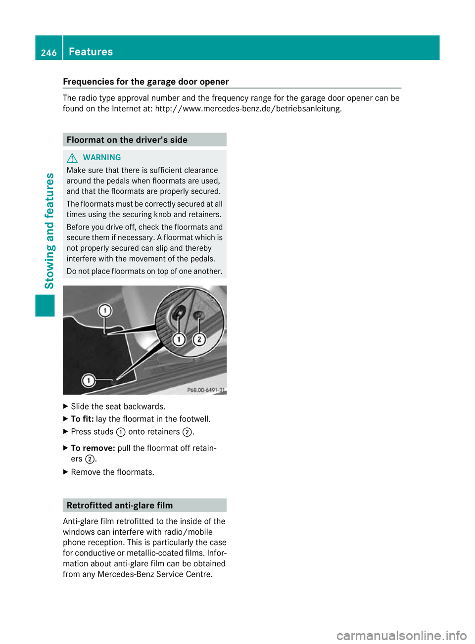
Do not place floormats on top of one another. X
Slide the seat backwards.
X To fit: lay the floormat in the footwell.
X Press studs :onto retainers ;.
X To remove: pull the floormat off retain-
ers ;.
X Remove the floormats. Retrofitted anti-glare film
Anti-glare film retrofitted to the inside of the
windows can interfere with radio/mobile
phone reception. This is particularly the case
for conductive or metallic-coated films. Infor-
mation about anti-glare film can be obtained
from any Mercedes-Benz Service Centre. 246
FeaturesStowing and features
Page 262 of 321
Useful information
............................260
Where will I find...? ...........................260
Flat tyre ............................................. 263
Battery ............................................... 273
Jump-starting .................................... 277
Towing and tow-starting ..................278
Electrical fuses ................................. 281 259Breakdown assistance
Page 264 of 321
X
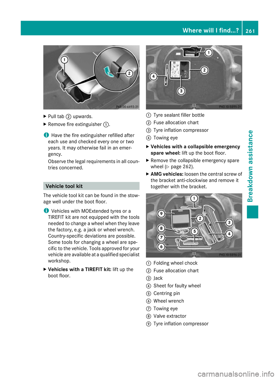
Pull tab ;upwards.
X Remove fire extinguisher :.
i Have the fire extinguisher refilled after
each use and checked every one or two
years. It may otherwise fail in an emer-
gency.
Observe the legal requirement sinall coun-
tries concerned. Vehicle tool kit
The vehicle tool kit can be found in the stow-
age well under the boot floor.
i Vehicles with MOExtended tyres or a
TIREFIT kit are not equipped with the tools
needed to change a wheel when they leave
the factory, e.g. a jack or wheel wrench.
Country-specific deviations are possible.
Some tools for changing awheel are spe-
cific to the vehicle. Tools approved for your
vehicle are available at a qualified specialist
workshop.
X Vehicles with a TIREFIT kit: lift up the
boot floor. :
Tyre sealant filler bottle
; Fuse allocation chart
= Tyre inflation compressor
? Towing eye
X Vehicles with acollapsible emergency
spare wheel: lift up the boot floor.
X Remove the collapsible emergency spare
wheel (Y page 262).
X AMG vehicles: loosenthe central screw of
the bracket anti-clockwise and remove it
together with the bracket. :
Folding wheel chock
; Fuse allocation chart
= Jack
? Sheet for faulty wheel
A Centring pin
B Wheel wrench
C Towing eye
D Valve extractor
E Tyre inflation compressor Where will I find...?
261Breakdown assistance
Page 265 of 321
Collapsible emergency spare wheel
Removing the collapsible emergency
spare wheel The collapsible emergency spare wheel can
be found in the stowage well unde rthe boot
floor.
AMG vehicles: the collapsible emergency
spare wheel is packed in a bag and secured
to a bracket in the boot. Example
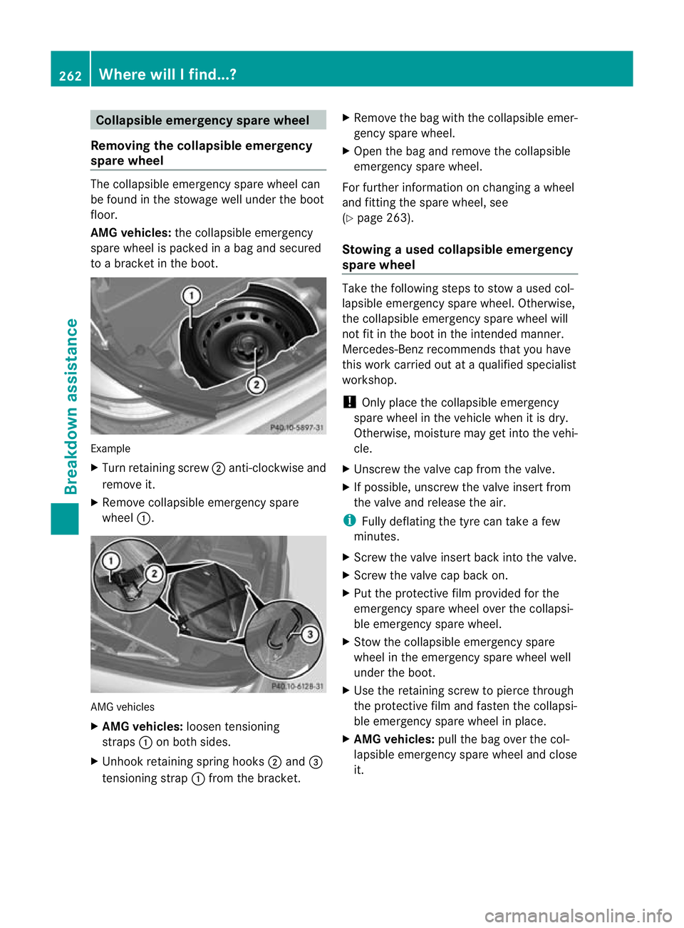
X
Turn retaining screw ;anti-clockwise and
remove it.
X Remove collapsible emergency spare
wheel :. AMG vehicles
X
AMG vehicles: loosen tensioning
straps :on both sides.
X Unhook retaining spring hooks ;and =
tensioning strap :from the bracket. X
Remove the bag with the collapsible emer-
gency spare wheel.
X Open the bag and remove the collapsible
emergency spare wheel.
For further information on changing a wheel
and fitting the spare wheel, see
(Y page 263).
Stowing aused collapsible emergency
spare wheel Take the following steps to stow a used col-
lapsible emergency spare wheel. Otherwise,
the collapsible emergency spare wheel will
not fit in the boot in the intended manner.
Mercedes-Benz recommends that you have
this work carried out at a qualified specialist
workshop.
!
Only place the collapsible emergency
spare wheel in the vehicle when it is dry.
Otherwise, moisture may get into the vehi-
cle.
X Unscrew the valve cap from the valve.
X If possible, unscrew the valve insert from
the valve and release the air.
i Fully deflating the tyre can take a few
minutes.
X Screw the valve insert back into the valve.
X Screw the valve cap back on.
X Put the protective film provided for the
emergency spare wheel over the collapsi-
ble emergency spare wheel.
X Stow the collapsible emergency spare
wheel in the emergency spare wheel well
under the boot.
X Use the retaining screw to pierce through
the protective film and fasten the collapsi-
ble emergency spare wheel in place.
X AMG vehicles: pull the bag over the col-
lapsible emergency spare wheel and close
it. 262
Where will I find...?Breakdown assistance
Page 281 of 321
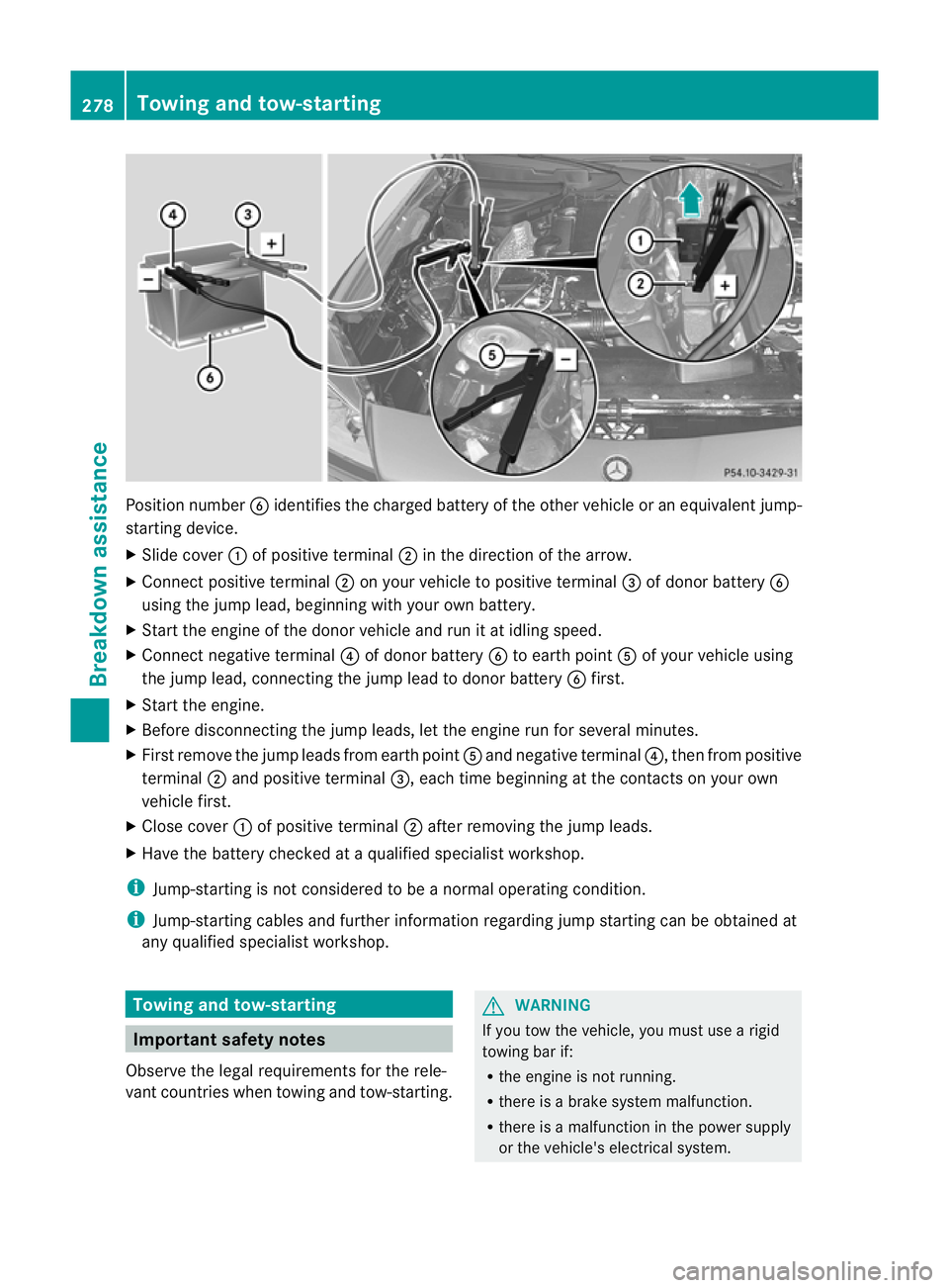
Position number
Bidentifies the charged battery of the other vehicle or an equivalent jump-
starting device.
X Slide cover :of positive terminal ;in the direction of the arrow.
X Connec tpositive terminal ;on your vehicle to positive terminal =of donor battery B
using the jump lead, beginning with your own battery.
X Start the engine of the donor vehicle and run it at idling speed.
X Connect negative terminal ?of donor battery Bto earth point Aof your vehicle using
the jump lead, connectingt he jump lead to donor battery Bfirst.
X Start the engine.
X Before disconnecting the jump leads, let the engine run for several minutes.
X First remove the jump leads from earth point Aand negative terminal ?, then from positive
terminal ;and positive terminal =, each time beginning at the contacts on your own
vehicle first.
X Close cover :of positive terminal ;after removing the jump leads.
X Have the battery checked at a qualified specialist workshop.
i Jump-starting is not considered to be a normal operating condition.
i Jump-starting cables and further information regarding jump starting can be obtained at
any qualified specialist workshop. Towing and tow-starting
Important safety notes
Observe the legal requirements for the rele-
vant countries when towing and tow-starting. G
WARNING
If you tow the vehicle, you must use a rigid
towing bar if:
R the engine is not running.
R there is a brake system malfunction.
R there is a malfunction in the power supply
or the vehicle's electrical system. 278
Towing and tow-startingBreakdown assistance